
The SV203 powered PPRKCircuit With Devantech SRF04 UltraSonic Sensor

The circuit utilizes the Devantech SRF04 Ultrasonic Sensor, which is designed for distance measurement using ultrasonic waves. The sensor operates by emitting a high-frequency sound pulse and measuring the time it takes for the echo to return after bouncing off an object. The minimum initiation time of 10 milliseconds ensures that the sensor is ready to trigger a new measurement after completing the previous cycle.
In the schematic, the SRF04 is connected to the SV203, which serves as the control unit for processing the sensor's readings. The trigger pin of the SRF04 is connected to a microcontroller or a logic circuit that sends a low signal to initiate the measurement process. The echo pin of the SRF04 receives the reflected signal, which is then processed to calculate the distance based on the time delay of the echo.
The inclusion of passive components such as capacitors and resistors ensures stable operation and signal conditioning, while the transistor may be used to amplify the signal or control the power to the sensor. The battery provides the necessary power supply, ensuring that the circuit operates efficiently.
This circuit design is suitable for applications requiring distance measurement and obstacle detection, making it valuable in robotics, automation, and various sensing applications. The straightforward nature of the circuit allows for easy implementation and integration into larger systems.The following circuit shows about Devantech SRF04 UltraSonic Sensor To The SV203 powered PPRK Circuit Diagram. This circuit based on the Devantech SRF04 sensor. Features: minimum of 10m sec to initiate the sonic pulse ( the trigger), fairly simple, held low (logic 0) input line.
Component: Capacitor, Resistor, Junk, IC, Battery, Infra red, Transistor. [ cs. uga. edu ] 🔗 External reference
Related Circuits
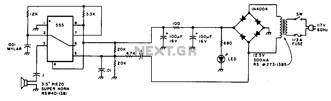
Low-intensity ultrasonic sound waves in the 30-45 kHz frequency band repel insects and small rodents. The unit is designed to generate a swept square wave from 30 to 45 kHz. The LM555 integrated circuit (IC) is configured as an...
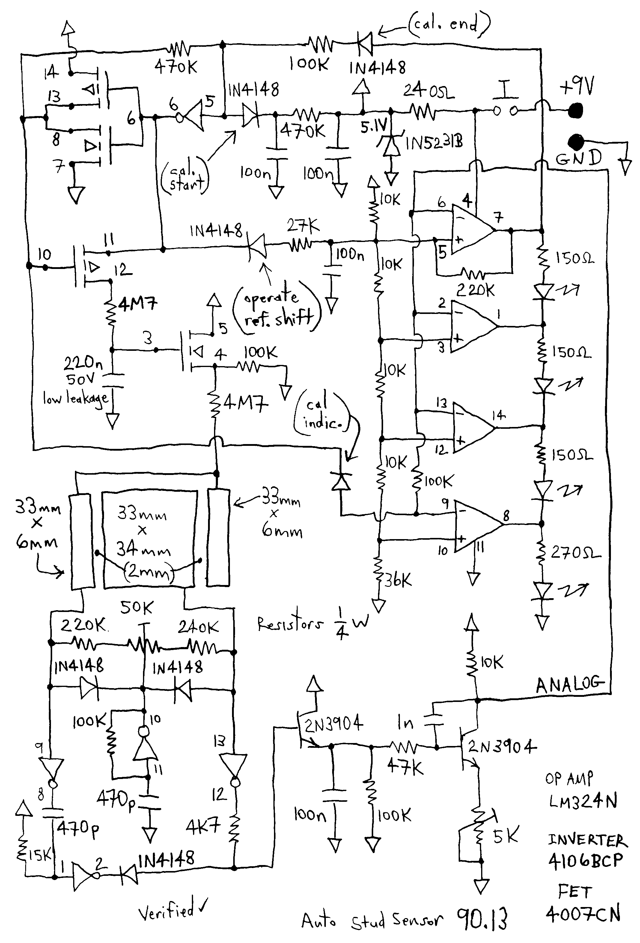
This thing is a very nifty capacitive sensor. For you europeans, this little gem is used in north america mostly for detecting wooden beams behind drywall or plaster. I'll take one of these over the new design any day,...
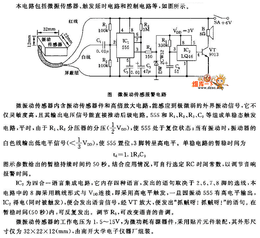
This circuit features a micro vibration sensor, a trigger delay circuit, and a control circuit, as illustrated in the accompanying figure. The micro vibration sensor comprises a vibration sensing device and a high power amplifier circuit, enabling it to...
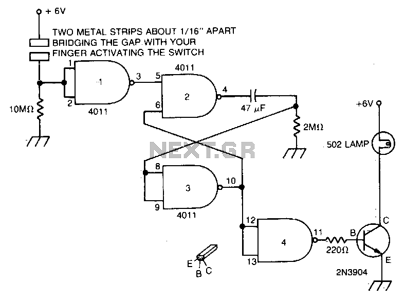
Touch the plate, and the light will turn on and remain on due to the 47 µF capacitor and the 2MΩ resistor for a duration determined by the timing resistor. The circuit described involves a touch-sensitive plate that activates a...
This two-part article explains the utilization of a simple voltage divider circuit incorporating a thermistor to obtain high-accuracy temperature readings across a wide range of measurements. The first part focuses on the circuit design and explores various methods for...
T-121 temperature sensor electronic thermometer circuit diagram shown below The T-121 temperature sensor circuit is designed to measure and display temperature readings accurately. The circuit typically consists of a temperature sensor, such as the T-121, which converts temperature variations into...