
The uTracer V3 a miniature Tube Curve Tracer

The uTracer circuit design emphasizes safety and robustness, particularly in high-voltage applications. The boost converter's role in energy limitation is critical; the energy stored in capacitors poses a significant risk, necessitating careful consideration of component ratings and thermal management. The implementation of a current limiter within the high voltage switch is vital to prevent excessive current that could lead to thermal runaway or component failure. The rapid response of the microcontroller to overcurrent conditions further enhances the safety of the circuit, allowing for quick disconnection of the high voltage supply to minimize damage.
Galvanic isolation through opto-couplers is an essential feature that protects sensitive control circuitry from high voltage spikes, ensuring that a failure in the high voltage section does not compromise the integrity of the control system. The design also accounts for potential voltage elevation in the supply rail due to current dumping during fault conditions. This is particularly important in maintaining the operational stability of the entire system and protecting sensitive components from overvoltage conditions.
In summary, the uTracer V3 circuit design incorporates multiple layers of safety and robustness, including energy limitation, current limiting, rapid fault detection, and galvanic isolation, all aimed at preventing catastrophic failures while maintaining operational functionality. The careful consideration of component interactions and potential fault conditions is critical in high-voltage applications, emphasizing the need for thorough testing and validation of the circuit design.In an instrument like the uTracer, which handles voltages of several hundreds of Volts at currents of several hundreds of mA, it is obvious that an error or malfunction can easily result in the destruction of (a part of) the circuit, especially so since the uTracer is build up from sensitive semiconductors. I vividly recall how a malfunctioning high voltage switch in the version 1 uTracer resulted in a complete destruction of all the semiconductors in the circuit! Although I was under the impression that I had pretty well covered the issue of robustness in the current version 3, a remark made by one of the faithful readers of these pages, Martin Forsberg, caused me to re-think the whole robustness issue, and to make several important modifications. The operator of the uTracer can make a mistake. Especially when a wired tube connection system like I use is employed, this is not an unthinkable scenario.
Finally, the possibility should be considered that a part of the uTracer circuit itself fails. Even in that case the damage of such a mal function should be confined and not result in a destruction of the complete circuit or even worse, the PC connected to the uTracer. Figure 8. 1 shows in a simplified circuit diagram the most important components of the safety features that have now been incorporated into the present uTracer V3 to improve its robustness.
In block 1 we find the boost converter itself. Although this is not a safety feature in itself, the fact that the amount of energy stored in the capacitor is limited obviously greatly helps. But nevertheless, at a maximum voltage of 350 V, the energy stored in the 100 uF capacitor is 0. 5*C*VU= 6. 1 J. Although this is just enough energy to raise the temperature of 1 cc water 1. 5 degree, it can easily destroy a whole board of semiconductors! Block 2 in Fig. 8. 1 is the high voltage switch. In this block three safety features have been implemented which have already been discussed in one of the previous sections.
In the first place a current limiter limits the maximum anode / screen current to 250 mA. In the second place when an over current is detected, the microcontroller shuts-off the high voltage switch in ca. 50 us. Finally, the complete high voltage switch is galvanically isolated from the rest of the circuit by means of an opto-coupler.
This isolates the micro-controller from the high voltage switch in case of a malfunction or breakdown of the high voltage switch itself. Block 3 in Fig. 8. 1 needs some explaining. In section 2 of this page it was explained that by referencing the cathode to the supply voltage rather than to ground it becomes possible to apply anode voltages down to zero.
We have already seen that it is very simple to protect the filament driver circuit against high voltages by clamping the filament terminals to the cathode with two diodes (D4, D5), or in other words to the supply rail. Similarly the grid bias circuit can also be protected with a simple clamp diode (D6). The consequence is however that both during normal operation, as well as when the protection diodes are activated, the current is dumped into the supply rail rather than to ground!
Potentially this can lift the supply rail and in that way cause damage to the rest of the circuit or even the power supply. In the further discussion of the consequences we consider two cases. In the first case the high voltage switch and current limiting circuit function as they should. This means that the maximum current is 250 mA for a pulse duration of 1 ms. Under these normal circumstances it should be sufficient to simply decouple the power supply with a large capacitor of say 1000 uF.
A pulse of 250 mA for 1 ms in a 1000 uF capacitor will result in a voltage increase of only (0. 25*0. 001)/0. 001 = 0. 25 V. However, let`s now assume that for one reason or the other the high voltage switch fails, so 🔗 External reference
Related Circuits

The +/- 3 dB point for the treble is approximately 2.5 kHz, with a boost/cut of about 12 dB at 10 kHz. It may be necessary to check the wiring or component values. Access to a signal generator is...
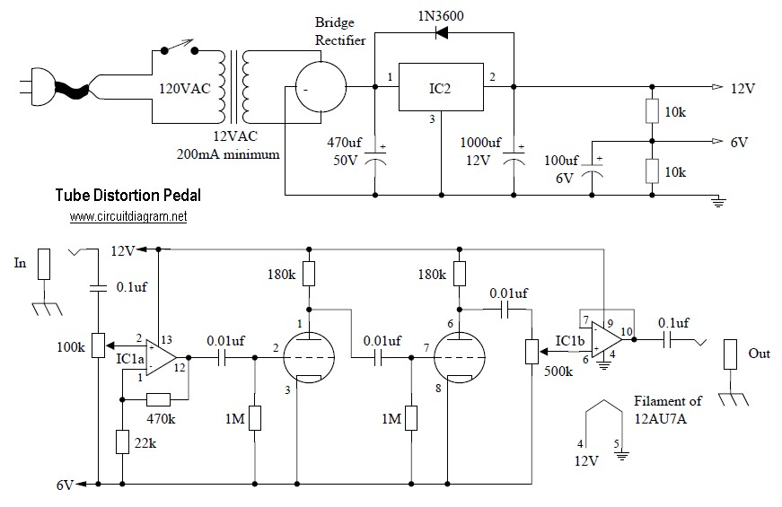
Tube distortion pedal circuit diagram. IC1: 747 dual op-amp; other ICs may be substituted, but the pinout will differ, so the datasheet should be checked. IC2: LM340K-12V voltage regulator. All resistors are 1/2 W. The bridge rectifier is a...
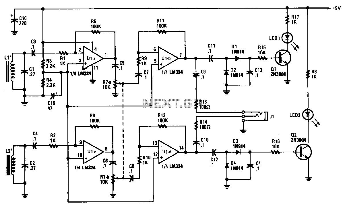
The tracer receiver is a stereo audio amplifier and detector circuit that operates at a frequency close to 1 kHz. Inductors L1 and L2 are hand-wound coils, each consisting of 200 turns of #26 wire on 2-inch ferrite cores,...
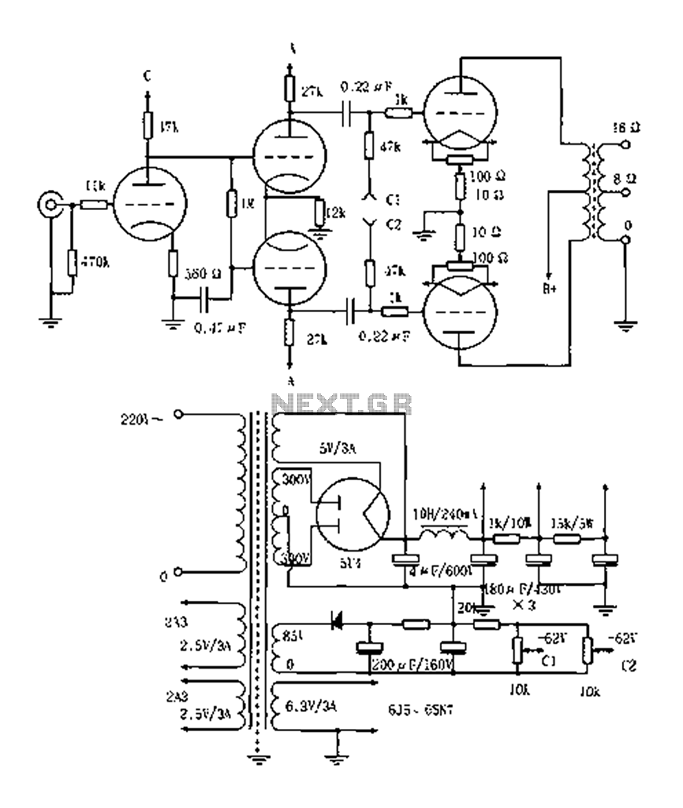
The Elliot 2A3PP line amplifier is a straightforward design, emphasizing the quality of the output transformer. It utilizes a 3KPP output transformer with a fixed bias of 62V, delivering an output power of 15W. The 2A3PP is well-suited for...
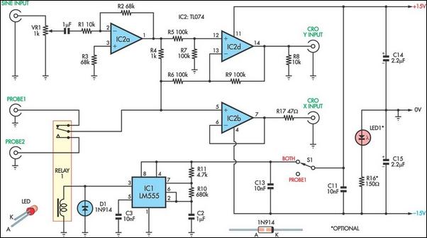
This unit utilizes a dual trace oscilloscope with X-Y functionality as a display to test and demonstrate the operation of circuits and components such as transistors, diodes, zener diodes, and both terminated and unterminated transformers. A low-frequency sine wave...

This is one of many available variations for a Symmetrical SRPP Preamplifier based on the 6DJ8 / ECC88 family of tubes. The SRPP circuit has also been referred to as a SEPP, Totem Pole, Mu Follower, Mu amplifier, and...