
Tube preamp tone control

The described circuit appears to be a tone control section of an audio preamplifier, specifically focusing on treble and bass adjustments. The treble control is designed to adjust the frequency response at higher frequencies, with a specified behavior at 2.5 kHz and 10 kHz. The presence of an "Ultra High" switch suggests an additional feature intended to enhance treble frequencies, but its ineffectiveness indicates potential issues within the circuit.
The simulation results provide insight into the circuit's behavior under various conditions, indicating that the treble response is highly dependent on the volume control settings. This dependency highlights the importance of ensuring that the operational parameters of the circuit are well understood and optimized for desired audio performance.
The use of linear potentiometers in lieu of logarithmic ones may also contribute to the observed issues, as logarithmic pots are typically preferred in audio applications for their more natural response to human hearing. The suggestion to check the tube voltages is critical, as the ECC83 (12AX7) tubes play a significant role in the gain and overall tonal characteristics of the circuit. Ensuring that the tubes are functioning correctly and within specified voltage ranges is essential for achieving the expected performance.
Furthermore, the output impedance of the tone control circuit must be matched with the load impedance to avoid loading effects that could degrade the audio signal. The recommendation to simulate the circuit with various component values using a tone stack simulator is a practical approach to fine-tuning the response characteristics and achieving the desired tonal balance.
In conclusion, the successful operation of this tone control circuit hinges on careful attention to component selection, circuit configuration, and thorough testing to ensure that all elements are functioning as intended. Proper troubleshooting and adjustments based on simulation data will facilitate optimal performance and enhance the overall audio experience.The +/- 3 dB point for the treble is about 2, 5 KHz, with about 12 dB boost/cut at 10 KHz. Perhaps you should check the wiring (again ) or perhaps componentvalues Do you have access to a signal generator yeah i checked wiring and components again and again, i used linear pots cuz there s no log pot here, but still it s not working, in fact the the u-hi switch has a very very small change in output tone too, i donno where s the problem in treble section. i used regular caps in whole circuit, should i use anything special But first: I presume that "Ultra High" switch is meant for some high treble accentuation (presence ), but it does not do that at all! I simulated your circuit on a computer programme. Firstly, the U-H circuit will be volume control dependent as you are probably aware of. But with the volume control set about half-ways, the treble is +3 dB already at a frequency of 650 Hz, and 8 dB up at 10 KHz.
With the volume control further down (15% from 0), the +3 dB point is 400Hz and the response at 10 KHz up by 15 dB. That is not at all "ultra-high", and also quite a substantial treble increase! I would imagine you can do without it at all, but let us at least do things one at a time, and keep that switch off until the rest of the pre-amp is working.
Also then, with the substantial difference that switch should make but does not, may I suggest you first check whether the tubes are working at all, i. e. measure the voltages (with a digital meter if you can). I would place the ECC83 anode voltages at 90V - 150V, with the cathodes at a volt or two. Use the signal generator to determine that you have reasonable gain at all. Do you have a scope Further to that you can check the tone control circuit alone, by detaching it from the 2nd ECC83 anode and feeding it directly with your signal generator.
(Now you will need a scope. ) The treble should give a response between +/- 8 dB or so at 10 KHz. Two final points, which I should maybe have asked first. You mention only the treble; does the bass control work adequately Then I see the circuit you use (the first one quoted) feeds out into whatever load you have, without another isolating stage (the circuit giving the values has further stages which I understand you do not use). Be aware that for proper operation of the tone controls the "load" you feed them into must have an impedance of at least 500K or more.
(The output impedance of your tone control alone is 140K, which must not be loaded appreciably otherwise the response will suffer. ) I ran a simulation of the circuit using Multisim 8 and the treble control does indeed do almost nothing (treble cut only) I then tried the values shown for the James tone stack in Duncans tone stack simulator and these values worked much better.
If you don`t already have it download a copy from Duncan`s site and use it to try different values I`m sure you will find something that works. Before we confuse Ahmad; Retailer, I have simulated the tone control section only, on P. Spice, using in serie with the signal generator an input resistance of 120K to the tone circuit proper, to guestimate a rather high rp from the tube (because of current feedback) somewhat shunting the plate load of 150K.
(It might well be a little lower than 120K. ) Relative to 1 KHz I found for full treble boost a +3 dB point at 3, 2 KHz, with 10 dB boost at 10 KHz and climbing. Going to full treble cut I found a -3 dB point at 5, 2 KHz, with treble cut at 10 KHz of 7, 3 dB and decreasing.
The tone control output was unloaded and the bass control at mid-point. This represents the normal somewhat unsymmetrical response typical of this type of passive tone control. (I also found the bass variation somewhat overpowering and 🔗 External reference
Related Circuits
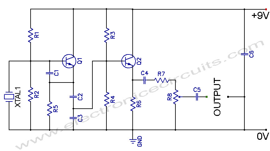
Crystal Controlled Oscillator Circuit. This general-purpose signal source is highly effective in signal-tracing applications. The output level is adjustable. The crystal-controlled oscillator circuit is designed to provide a stable and precise frequency output, which is essential for various electronic applications,...
This Project is made up with AT89C2051 and the RTC DS1307. It has a large Seven segment display. The standard remote control is used to change the Time. More: Procedure to enter the Time 1. Press power button on...
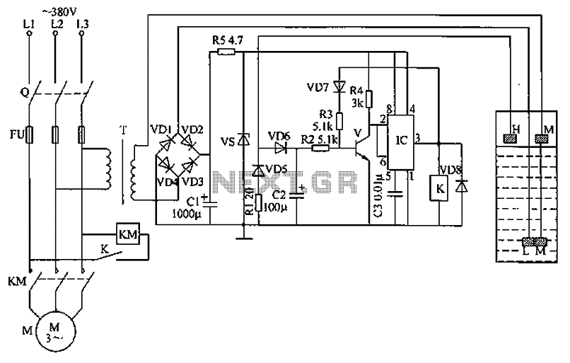
The circuit functions as a liquid level automatic controller, comprising a power circuit, a level detection circuit, and a control execution circuit. The power circuit includes a knife switch (Q), fuse (FU), power transformer (T), rectifier diodes (VD1 to...
The circuit above illustrates using the IR receiver module along with a PIC12F629 microcontroller to decode 5 individual IR remote control keys so the circuit will only toggle one of the 4 outputs when a particular key is pressed....
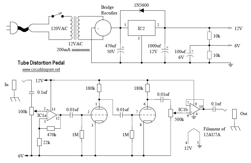
Tube distortion pedal circuit diagram. IC1: 747 dual op-amp; other ICs may be substituted, but the pinout will differ, so the datasheet should be checked. IC2: LM340K-12V voltage regulator. All resistors are 1/2 W. The bridge rectifier is a...
This page outlines the modifications made to a SkyWatcher dual-axis EQ5/EQ4 motor controller to enable autoguiding via the parallel port from a PC. The modification allows the RA+, RA-, Dec+, and Dec- buttons to be activated from the PC...