
The Zener-based solar engine

The described circuit operates as a simple motor control mechanism utilizing a PNP and an NPN transistor configuration. The PNP transistor (2N3906 or BC327) is responsible for initial activation, while the NPN transistor (2N3904 or BC337) handles the power delivery to the motor.
Initially, the capacitor charges through a resistor until the voltage across it reaches a level sufficient to forward-bias the base-emitter junction of the PNP transistor. The Zener diode in the circuit serves to regulate the voltage applied to the base of the PNP transistor, ensuring that it turns on at a specific threshold voltage. Once the PNP transistor is activated, it allows current to flow from the collector to the emitter, which in turn provides base current to the NPN transistor through the 2.2K resistor.
As the NPN transistor turns on, it creates a low-resistance path from the collector to the emitter, enabling the capacitor to discharge rapidly through the motor connected to the NPN's collector. This discharge provides the necessary current to drive the motor, effectively turning it on. The action of the NPN transistor also reinforces the PNP transistor's conduction, creating a regenerative feedback loop that keeps the circuit in an 'on' state until the capacitor discharges below a certain threshold.
Overall, this configuration allows for a controlled and efficient method to activate a motor using capacitive discharge, leveraging the properties of both transistor types to achieve reliable operation.The capacitor charges until the PNP transistor (here shown as a 2N3906, but you could also use a BC327) receives base current through the Zener and turns on. Then the NPN transistor (here shown as a 2N3904, but you could also use a BC337) turns on and the capacitor is discharged through the motor.
As the NPN turns on the 2.2K resistor starts to supply base current to the PNP and the circuit snaps on. 🔗 External reference
Related Circuits
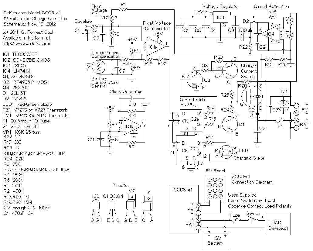
The SCC3 is a solar charge controller. Its function is to regulate the power flowing from a photovoltaic panel into a rechargeable battery. It features easy setup with one potentiometer for the float voltage adjustment, an equalize function for...
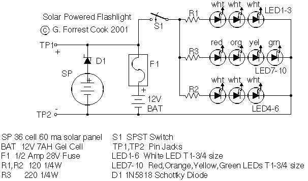
Tired of always spending money on flashlight batteries only to have them fail just when you need them? Try this simple circuit out. It would make an excellent science fair project. The white LEDs are quite bright, they provide...
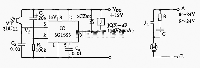
The control circuit consists of an NE555 timer and a phototransistor, along with resistors R1, capacitors C1 and C2, among other components. The photodiodes 3DU12 respond to sunlight by decreasing their resistance, which causes the voltage at the 555...
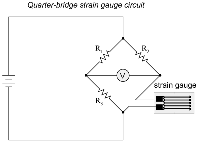
When a strip of conductive metal is stretched, it becomes thinner and longer, resulting in an increase in electrical resistance along its length. Conversely, when the strip is subjected to compressive forces (without buckling), it will widen and shorten....
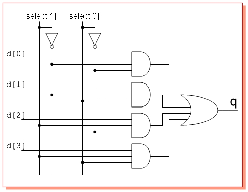
Design a circuit with four single-bit inputs X, Y, T, and Z, and a single-bit output E. A two-bit control code word S0S1 determines which of the four inputs is sent to the output (the selection code is not...
The simplest current-to-voltage (I to V) converter is a basic resistor. However, the disadvantage of this simple configuration is that it presents a nonzero impedance to the input current source. The I to V converter is an essential circuit in...