
Photovoltaic (Solar Cell) Current To Voltage Converter
 Current To Voltage Converter")
The I to V converter is an essential circuit in various electronic applications, particularly in sensor interfacing and signal conditioning. In the simplest form, a resistor is used to convert an input current (I) into a proportional output voltage (V) according to Ohm's law, where V = I × R. Here, R represents the resistance value in ohms.
Despite its simplicity, using a resistor as an I to V converter has significant drawbacks due to its inherent nonzero impedance. This nonzero impedance can affect the accuracy of the conversion, especially when interfacing with high-impedance sources or sensitive measurement devices. The output voltage may not accurately reflect the input current if the source cannot drive the load effectively due to the voltage drop across the resistor.
To mitigate these issues, more advanced I to V converter designs often employ operational amplifiers (op-amps) in an inverting configuration. This configuration provides a high input impedance, ensuring minimal loading on the input current source. The op-amp can convert the input current into a voltage output with high accuracy and stability, making it suitable for a wide range of applications, including analog signal processing, data acquisition systems, and instrumentation.
In summary, while a simple resistor can serve as an I to V converter, its limitations necessitate the use of more sophisticated designs, such as those utilizing op-amps, to achieve better performance and reliability in practical applications.The simplest I to V converter is the humble resistor. However, presenting a nonzero impedance to the source of input current is the disadvantage of the humble. 🔗 External reference
Related Circuits
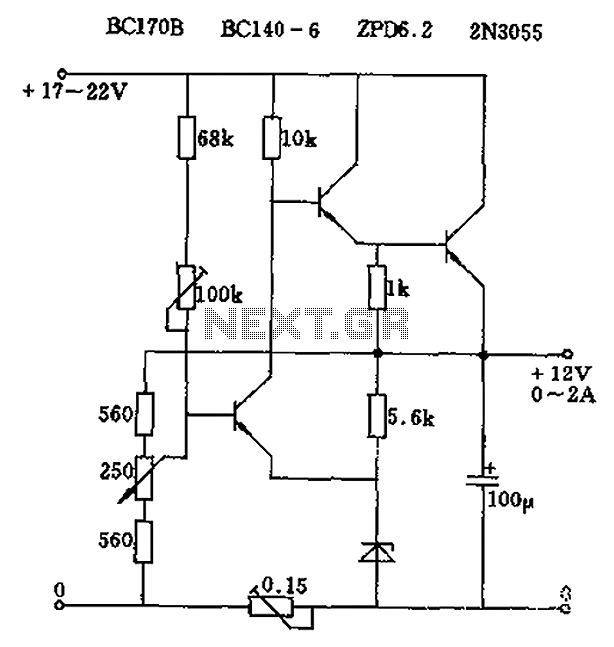
The circuit output voltage can be continuously adjusted from zero to its maximum value. The baseline is established by a constant current sourced from the auxiliary power supply circuit. The reference current of 500 microamperes can be fine-tuned to...
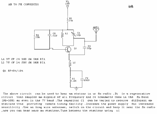
This circuit can be used to receive AM stations in an FM radio. It is a regenerative circuit that samples AM signals of all frequencies and retransmits them in the FM band or in the TV band. The described circuit...

The hobby circuit described utilizes a unique approach to generate approximately 12,000 volts with a current of about 5 µA. It employs two silicon-controlled rectifiers (SCRs) that form dual pulse generator circuits. These SCRs discharge a 0.047 µF capacitor...
A simple voltage status monitor built around the LM741 operational amplifier. These circuits are recognized for their accuracy, ease of operation, and cost-effectiveness. The LM741 serves as an operational amplifier, widely used for various applications. The primary function of...
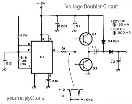
The schematic diagram originates from a 12V DC voltage doubler circuit power supply. This circuit diagram illustrates a DC voltage doubler/DC converter that transforms a 12V DC power supply into 24V DC and 18V DC outputs. It is compatible...
Through simple circuit modifications, designers can use peak current limiting to produce a constant current source. A constant current source is an essential component in various electronic applications, providing a steady output current regardless of load fluctuations or variations in...