
There are preamplifier with four inputs

The hybrid circuit represented in Figure 3-25 is designed to accommodate a variety of audio input sources while maintaining signal integrity through isolation and compensation techniques. The use of an inverting operational amplifier as a proportional adder allows for the seamless summation of multiple audio signals, making it particularly useful in applications such as broadcasting, recording, and live sound reinforcement. The layout of the input stages ensures that each source can be independently adjusted without affecting the others, a critical feature in multi-source environments.
The automatic compensation circuits for both treble and bass frequencies enhance the overall audio quality by maintaining a balanced sound profile, regardless of the volume level. This feature is particularly beneficial in professional audio applications where consistent sound quality is paramount. The adjustable resistors and capacitors allow for fine-tuning of the circuit, enabling it to cater to various input sensitivities and signal characteristics.
Furthermore, the choice of the TL084 operational amplifier ensures that the circuit operates efficiently across a wide frequency range, making it suitable for high-fidelity audio applications. The design considerations, including the shielding of input elements and grounding practices, further contribute to the circuit's resilience against noise and interference, ensuring high-quality audio output.
In summary, the hybrid circuit in Figure 3-25 exemplifies a versatile solution for audio signal processing, integrating advanced features that enhance functionality, performance, and user control in professional audio environments.Figure 3-25 is a hybrid having four input preamplifier, in the circuit, cZ1, cz, C23 and cz4 respectively, can enter the microphone, line, phono and crystal head signal. Quad c an enter individually or simultaneously four mixed input, but also for dubbing the program needed chipped commentary and other editing. Enter either alone or in combination input, nothing happens to them between each other. The preamplifier input is applied the principle of proportional adder inverting operational amplifier, when several signals simultaneously input Pops, the output voltage is equal to the sum of each of the input voltage.
While at the inverting input of the operational amplifier summing point of virtual ground, and therefore between the respective input signal is isolated from each other when the input signal is a road 0:00, the input voltage across the resistor is also zero, so it does not affect the work of other separate ways o to accommodate each source input voltage is different, four input interface uses a different structure and number of circuit elements value, while also adding additional input required. The input interface circuit component values are shown in the diagram in accordance with the subject of the input signal sensitivity calculations.
If the actual figure depending on the input with the standard values can be properly adjusted R2, R, R6, or where the resistance can be. When C24 as head input, Ra take 1kfl, thus attenuating the treble, treble end of the play frequency equalization effect o volume control potentiometer RPi and Rl1, C treble consisting of automatic compensation circuit; RPi and Rt2, c9, Rl3 form a low tone automatic compensation circuit.
When RPl turn up the volume the more hours, the larger the amount of compensation Pak compensation circuit, therefore, adjust the sound volume when, without resetting the pitch controller.. SA control switch for the compensation circuit. RC network composed of five sections of the equalization circuit, adjust the range of 12dB. czJ and C24 high sensitivity, large-amplitude signal can not accidentally access lines, etc., so as not to damage the amplifier overload and bad.
No C24, the commissioning should point J disconnected. In order to reduce hum and induced noise, (: zl ~ C24 and an input element should be shielded metal cover, and good well grounded input signal line should be used in all metal shielded wire, and the end is well grounded. Circuit adoption of better performance quad op amp TL084, has good frequency response of the input line, the passband bandwidth of approximately 20Hz ~ 20kHz, distortion 0.5% o
Related Circuits
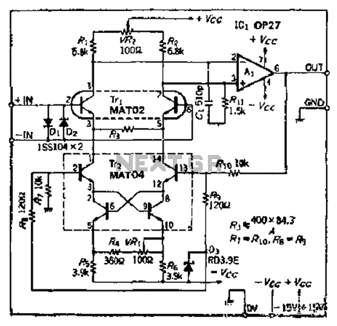
The Bong ordinary differential amplifier circuit differs from a standard differential circuit by incorporating a voltage-current conversion circuit, which consists of resistors R and Rl. The operational amplifier (OP amp) includes a voltage divider that subsequently converts the voltage...
Although many album titles that were once available on vinyl are gradually being released on CDs, not all titles are accessible. It is possible that there are valuable records in a collection that one might wish to convert to...
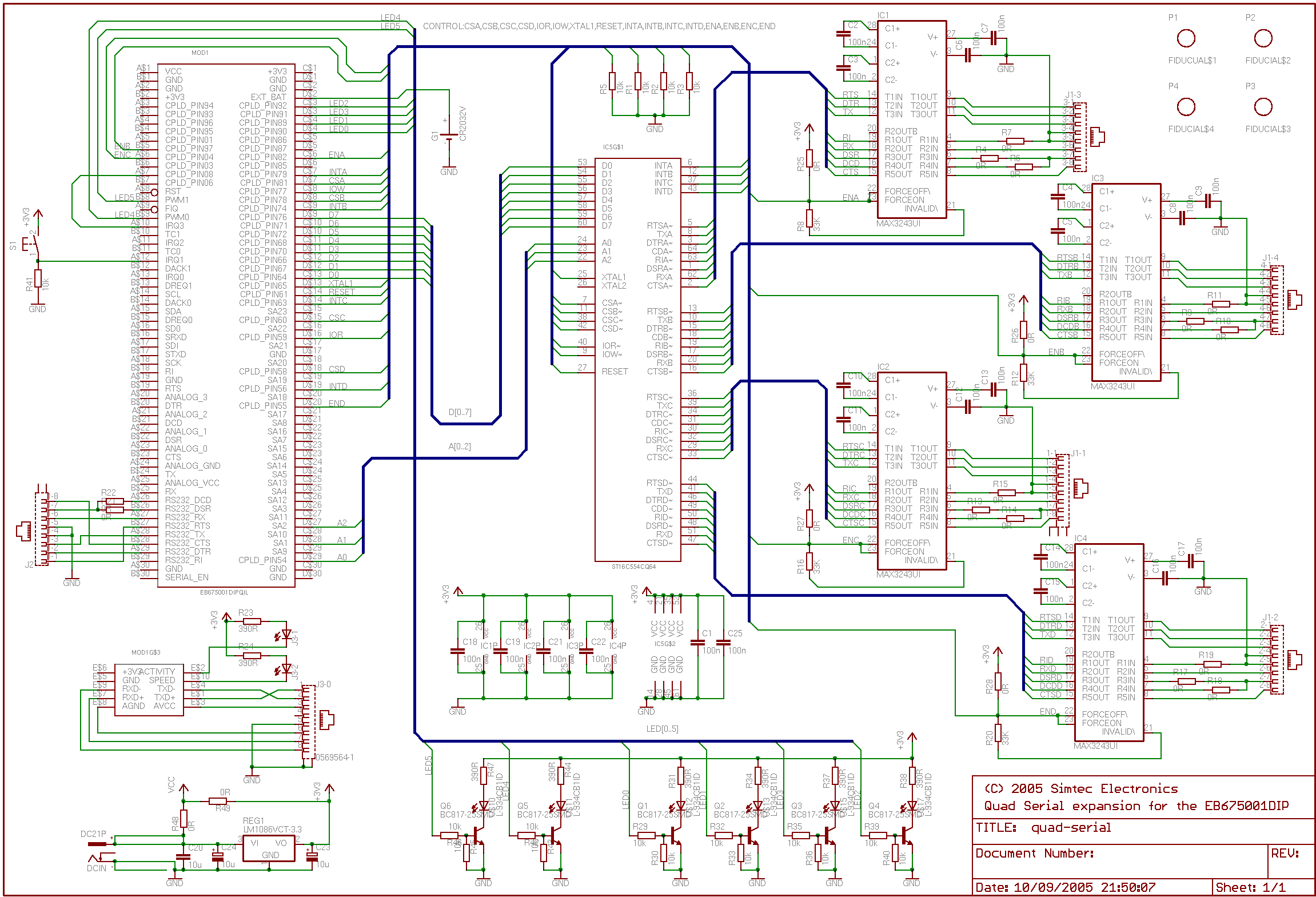
This application note details the integration of a quad serial controller into the EB675001 Module. A multi-source quad Universal Asynchronous Receiver and Transmitter (UART), specifically the 16554 type, was chosen to facilitate component sourcing and implementation. The RS232 line...
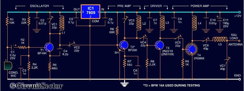
Here is the circuit diagram of a four RF stage FM transmitter. The stages include a very high frequency (VHF) oscillator built around the HF transistor BF494, a pre-amplifier using the BF200 transistor, a driver transistor 2N2219, and a...
This simple, inexpensive, wideband RF amplifier provides 14 dB gain on two meters without the use of tuned circuits. The RF amplifier described operates within the two-meter band, which typically spans frequencies from 144 to 148 MHz. It is designed...
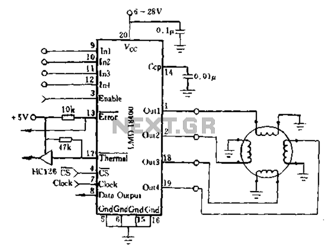
The DMOS power switch exhibits an ON-state resistance with a positive temperature coefficient, allowing for the parallel connection of four switches to increase load current, resulting in a monolithic design. The LMD18400 can drive one, two, or four small...