
Thermistor electronic thermometer circuit diagram

The described circuit employs a Wheatstone bridge configuration to accurately measure temperature variations through the thermistor RT. The resistors R1, R2, and R3 are arranged to form a balanced bridge at a reference temperature, typically set at 20°C. The variable resistor RP1 allows for fine-tuning of the balance, compensating for any discrepancies in resistor values or thermistor characteristics.
As the temperature rises, the thermistor RT's resistance decreases, causing the bridge to become unbalanced. This unbalance generates a differential voltage across the bridge's output terminals. The magnitude of this voltage change is proportional to the change in temperature, enabling precise temperature measurement.
The operational amplifier connected to the output of the bridge amplifies the differential voltage signal. This amplification is crucial for enhancing the sensitivity of the measurement, allowing for the detection of small variations in temperature. The output of the operational amplifier can be further processed or displayed, providing a clear indication of the measured temperature.
This circuit design is commonly used in temperature sensing applications, where accurate and responsive temperature readings are essential. The integration of the thermistor with the resistive network and operational amplifier ensures reliable performance across a range of temperatures.The thermistor RT and R1, R2, R3 and RP1 form a temperature measurement bridge. When temperature is at 20 ?, using R1, R3 and adjusting RP1 can allow bridge to keep balance. When temperature rises, the resistance of the thermistor RT reduces, the bridge in an unbalanced state, the imbalanced voltage output by bridge is amplified by operational amplifier, th.. 🔗 External reference
Related Circuits
The VFC62 is a voltage-to-frequency and frequency-to-voltage converter that effectively transforms analog signals into digital signals. The digital output is presented in an open collector format, where the digital pulse repetition rate is directly proportional to the amplitude of...
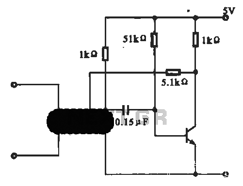
This circuit illustrates an oscillator that is controlled by an optocoupler, utilizing photoelectric coupling to drive a transistor. The oscillator circuit described operates by employing an optocoupler to provide electrical isolation between its input and output stages while allowing control...
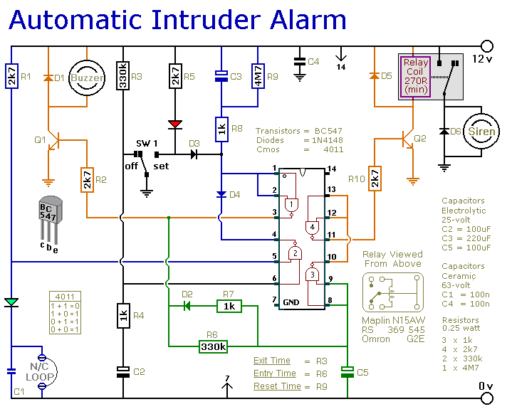
This is a simple single-zone burglar alarm circuit. Its features include automatic exit and entry delays and a timed bell/siren cut-off. It is designed to be used with the usual types of normally-closed input devices such as magnetic reed...
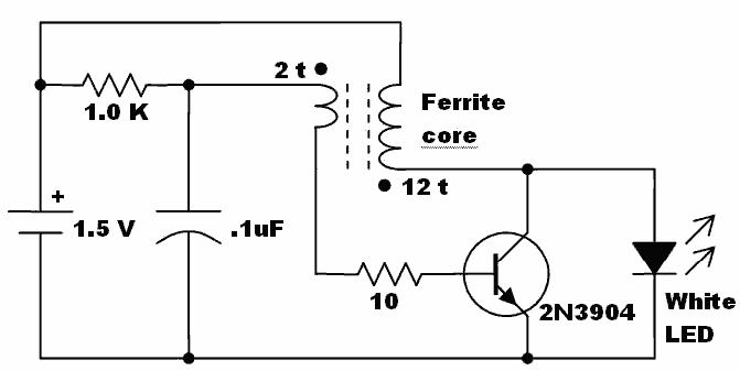
Here is an idea for a voltage booster that enables the lighting of a white LED using a single AA cell. This presents an opportunity to utilize one of the ferrite cores and white LED holiday lights mentioned in...

A highly accurate digital thermometer utilizing an LM35 probe with a resolution of 0.1 degrees Celsius. The circuit includes two adjustable components. The first, R5, is used to calibrate the display to zero. To perform this calibration, the end...

Battery charger utilizing solar and electrical power with a circuit diagram. This dual power source battery charger can charge a lead-acid battery using two different power sources. The battery charger circuit is designed to efficiently charge a lead-acid battery by...