
Oscillation circuit optocoupler control

The oscillator circuit described operates by employing an optocoupler to provide electrical isolation between its input and output stages while allowing control signals to pass through. The optocoupler consists of a light-emitting diode (LED) and a phototransistor, which work together to transfer signals via light rather than direct electrical connections. This configuration is particularly beneficial in applications where noise immunity and signal integrity are crucial.
In this circuit, the LED of the optocoupler is driven by a control signal. When the LED is activated, it emits light that is detected by the phototransistor, causing it to conduct. The conduction of the phototransistor is used to switch the oscillator circuit on or off, effectively modulating the output frequency based on the input control signal.
The oscillator itself may be designed using various configurations, such as a relaxation oscillator or a square wave generator, depending on the desired output characteristics. Common components used in the oscillator circuit include resistors, capacitors, and inductors, which determine the frequency and amplitude of the oscillations.
This design is advantageous in applications such as signal processing, where precise timing and control are necessary, as well as in power supply circuits where isolation is required to protect sensitive components from high voltages or noise. The use of an optocoupler in this manner enhances the reliability and performance of the oscillator circuit, making it suitable for a wide range of electronic applications.It shows the oscillator circuit optocoupler controlled by photoelectric coupling drive transistor.
Related Circuits
This heatsink temperature monitor circuit uses three LEDs to signal when the temperature exceeds two boundary levels. When the heatsink temperature is below 50-60°C (122-140°F), the green LED lights up. The yellow LED indicates that the temperature is between...
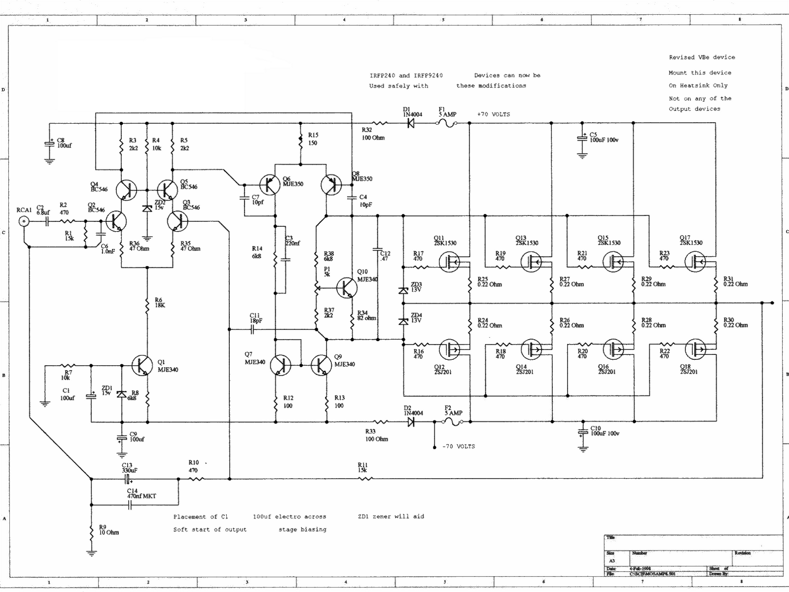
This is a simple LED-powered audio amplifier circuit utilizing a MOSFET amplifier with the TL071C operational amplifier. It can deliver up to 45 W into an 8-ohm load. The circuit incorporates the MOSFETs IRFP240 and IRFP9240, which are recommended...

A simple technique for measuring frequencies across a wide range with acceptable accuracy limits using a PC is presented. This method follows the basic principle of measuring low frequencies, where the period of a complete wave is measured and...
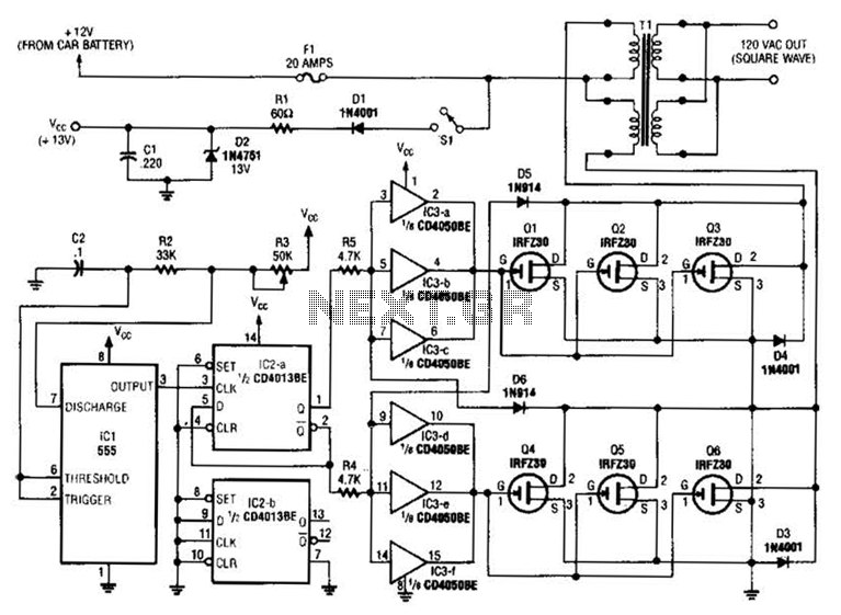
A 555 timer (IC1) generates a 120-Hz signal that is fed to a CD4013BE flip-flop (IC1-a), which divides the input frequency by two to generate a 60-Hz clocking frequency for the FET array (Q1 through Q6). Transformer T1 is...
This circuit consists of a light measurement circuit and a flash circuit, as illustrated in the accompanying figure. It is applicable in the POPTICS (a popular integrated camera), the Franka X-500, and the WIZEN-860S cameras. The light measurement circuit...
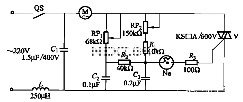
The 3P10 circuit, illustrated in the figure, utilizes a bidirectional thyristor for control. The adjustment potentiometer RPi allows for modification of the minimum motor speed, while the adjustment potentiometer RP2 enables continuous variation of the motor speed, reaching up...