
Thermometer with a LM335

The circuit described is a temperature measurement system utilizing the LM335 temperature sensor, which provides an output voltage linearly proportional to temperature. The output voltage of the LM335 is specified as 10 millivolts per degree Celsius. At a reference temperature of 25 degrees Celsius, the output voltage is calibrated to 2.982 VDC. This voltage serves as a baseline for temperature readings, and the circuit includes a reference circuit to establish a zero reference voltage, which is adjusted to 2.832 volts.
To directly measure the temperature in degrees Celsius, a high-impedance digital voltmeter (DVM) is employed. The positive lead of the DVM connects to the LM335 output pin, while the negative lead connects to the 2.732V reference output. This configuration allows for accurate temperature readings, as the output voltage is directly correlated to the temperature in degrees Celsius and Kelvin, with the understanding that the two scales differ only in their offsets.
Calibration of the circuit is critical for accurate temperature measurement. The initial step involves setting the output voltage at the "Output" pin to 2.982 volts when the LM335 is at the reference temperature of 25 degrees Celsius. Subsequently, a resistor, R2, is adjusted to achieve a voltage of 2.732 volts at the designated reference point. It is recommended that metal film resistors be used for the voltage divider to enhance accuracy, as they provide better stability and lower thermal coefficients compared to other resistor types.
The selection of components is also important for maintaining calibration stability. A high-quality potentiometer, such as a Beckman Helitrim pot, is suggested for R1 due to its mechanical stability under varying temperatures and low thermal coefficient of resistance. The choice of the LM335 sensor is significant, as it is available from reputable manufacturers like National Semiconductor and STMicroelectronics, ensuring reliability and performance.
In summary, this temperature sensor circuit, with its careful calibration and component selection, provides a reliable means of measuring temperature accurately in both Celsius and Kelvin, making it suitable for various applications where precise temperature monitoring is required.The circuit consists of two parts: The LM335 and its adjustment. The output of the LM335 is 10 millivolts per degree C, with 25 degrees C corresponding to 2.982 VDC. A reference circuit provides a zero reference voltage. It is adjusted to (2.982 volts - (25 degrees x 10 millivolts/degree) = 2.832 volts. To read the temperature of the LM335 directly in degrees C, connect the + lead from a high impedance DVM to the output pin and the - end of the DVM to the 2.732 volt pin. The factor of 10 millivolts per degree C is equivalent to 10 millivolts per degree K, since a change of one degree C is equal to a change of one degree K.
The difference in the two scales is only their offsets. The melting point of water ice is 0 degrees C and 273.15 degrees K. The boiling point of water is 100 degress C and 373.15 degrees K. Calibration: Set the voltage at the "Output" pin to 2.982 volts when the LM335 is at 25 degrees C. Adjust R2 to obtain 2.732 volts at the 2.732V output -this second adjustment is (ideally) independent of temperature. If you can get your hands on metal film resistors for the 2.732 volt divider, so much the better. Otherwise, adjust the 2.732 volt reference at the ambient temperature in which the thermometer is intended to be used.
Use a good quality pot for R1 because the circuit's calibration depends on it. I used a Beckman Helitrim pot, dug out of my junk box, as R1, because of this excellent mechanical stability with temperature change and well as a low thermal temperature coeficient of resistance. The LM335 is made by National Semiconductor and STMicroelectronics. I found the ones I bought at Arrow (http://www.arrow.com/) for only 65 cents each (plus the shipping charge).
They can also be found for sale on the National Semiconductor web site among others. I recommend the data sheet on the National Semiconductor site as the illustrations are clearer than those on the STMicroelectronics site. 🔗 External reference
Related Circuits
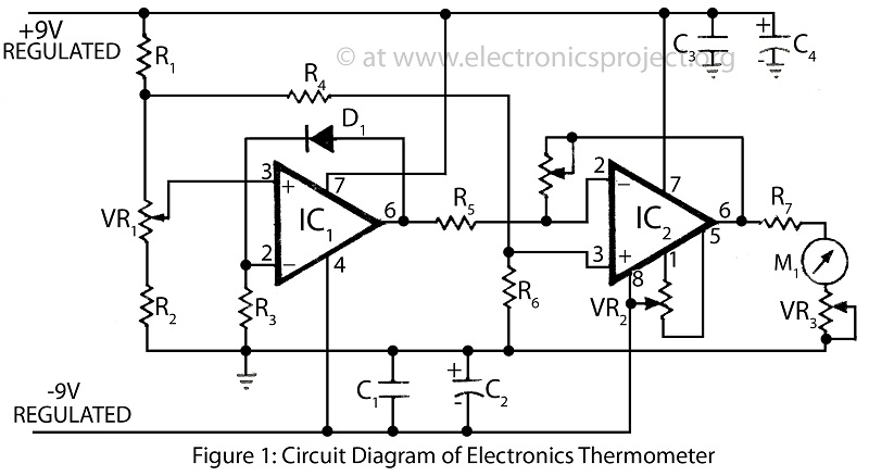
A clinical thermometer is typically used by doctors due to its complex reading mechanism. This circuit represents an electronic thermometer designed to measure a wide temperature range from -200°C to 1250°C. This single circuit electronic thermometer is capable of...

There are many digital thermometers with ±1°C displays, but their accuracy is approximately ±1°C and they cannot be calibrated. A thermometer circuit was created using components available at a local electronics hobby shop, providing an educational experience. For a...
This straightforward high-level design illustrates the structure of the product. The integrated circuit reacts to button presses and detects temperature through a probe, displaying the temperature on an LCD and activating a buzzer upon completion. A more detailed diagram...

Redesign a complex solution using minimal external components, resulting in a low-cost application that provides high-precision measurements. This digital thermometer microcontroller project utilizes a watchdog timer function to measure temperature. The watchdog timer (WDT) on all PIC microcontrollers has...
Temperature sensor converter designed for use with a digital multimeter, capable of measuring temperatures from -40 °C to 110 °C. It features a state indicator and requires no calibration, utilizing the LM35 integrated circuit. The freezing point of water...

This incredibly simple thermometer plugs on any free serial port. Does not make use of any programmable components as microcontrollers. It gives temperature readings accurate to 0.5°C with no calibration. It's cheap, so I've put one on any PC...