
Three-phase ac motor driver 2

The circuit described involves a frequency-adjustable oscillator that utilizes resistive components R1, R2, R3, and R4 to manipulate frequency and gain characteristics. The oscillator's frequency can be finely tuned through the adjustment of resistors R1 and R2, which are part of the timing network. By altering these resistors, the time constant of the oscillator circuit can be modified, thereby changing the frequency of oscillation within a specified narrow range.
The feedback mechanism in the oscillator includes two amplifiers, where the gain of the second amplifier is determined by the ratio of resistors R3 and R4. This gain adjustment is crucial for compensating for any signal loss that may occur within the phase shifters, ensuring that the output maintains integrity and desired amplitude levels.
Furthermore, the circuit has the capability to be externally driven by a pulse or square wave source. This feature allows the left-hand amplifier's gain to be set lower than the threshold required for self-oscillation, effectively stabilizing the circuit and preventing unwanted oscillations when external signals are applied.
The inclusion of RC feedback networks serves a dual purpose: they not only contribute to the overall feedback necessary for oscillation but also act as active filters. This filtering action is essential in shaping the output waveform, transforming it from potentially distorted signals into smooth sinusoidal outputs. The result is a well-defined oscillation that is suitable for various applications, including signal processing, waveform generation, and modulation tasks in electronic systems.By varying either Rl or R2, the oscillator frequency can be adjusted over a narrow range. The R3/R4 ratio sets the second amplifier's gain to compensate for signal attenuation occurring in the phase shifters. The circuits can be driven from an external source, such as a pulse or square wave, setting the gain of the left-hand amplifier to a level less than that required for oscillation.
The RC feedback networks then function as an active filter causing the outputs to be sinusoidal.
Related Circuits
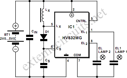
An EL lamp is a solid-state, low-power, uniform area light source. Due to its thin profile (as thin as 0.3 mm) and versatility in size and shape, EL lamps are ideal for providing backlighting for LCD displays, membrane keypads,...
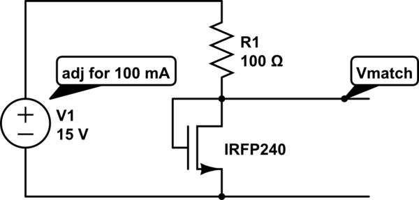
The unit is designed to drive an 80V/10A motor. The current matching circuit is utilized, but there is uncertainty regarding the appropriateness of the MOSFET selection for this application. The circuit for driving an 80V/10A motor typically requires careful consideration...
This is a discrete high-current switch-mode LED driver circuit. The fundamental principle of this circuit is based on the buck-converter topology. The efficiency of this circuit is 80%. The discrete high-current switch-mode LED driver circuit utilizes a buck converter configuration...
This integrated circuit is highly efficient and does not require any external glue logic for operation. It features two pins for motor control: one pin is dedicated to controlling the direction of the motor, while the other pin is...

An issue with CPLD and FPGA devices is that they have numerous I/O pins, resulting in schematics that quickly become overwhelmingly large. Different sections of the schematic have been partitioned to illustrate the motor control circuit, analog-to-digital converter circuit,...
This type of design can produce a very high amperage current for a fraction of a second that can be used to do some useful work if properly harnessed. The switching device could be a rotating spark gap as...