
FPGA DC Motor Control Circuit

The schematic for the motor control circuit integrates a CPLD (Complex Programmable Logic Device) and an FPGA (Field Programmable Gate Array), both of which are essential for managing various I/O operations. The large number of I/O pins associated with these devices necessitates careful organization of the schematic to avoid confusion. The motor control circuit, as the primary focus, is strategically designed to interface with the CPLD, which coordinates the motor's operation.
The inclusion of a capacitor near the motor controller IC is critical for maintaining a stable current supply to the motors, thus enhancing performance during operation. This capacitor acts as a filter, smoothing out any voltage fluctuations that may occur, which is particularly important during the rapid switching of the motor control signals.
The MAX150 component is utilized for its capability to continuously convert analog signals, ensuring that the data is promptly available for processing. The WR pin is a crucial control signal that triggers the MAX150 to update its output, allowing the CPLD to read the latest data without delay.
Furthermore, the PWM (Pulse Width Modulation) output capability of this circuit allows for simultaneous control of both the motors and the LEDs. This dual functionality not only provides visual feedback through LED brightness but also enables precise control of the motor's speed and direction. The schematic clearly delineates the connections between the CPLD, motor controller, and the LED outputs, ensuring that the design is both efficient and effective in its operation.
Overall, this schematic represents a well-structured approach to integrating complex components while maintaining clarity and functionality within the design.An issue with CPLD and FPGA devices is that they have so many I/O pins that their schematics become overwhemlingly HUGE very quickly. I tried my best to partition out different sections of the schematic to show the motor control circuit, a-to-d converter circuit and left-over LED output circuit.
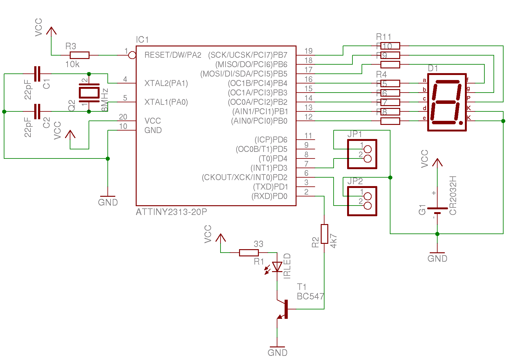
The motor control circuit is the main focus as it i s the new addition to this board. As you can see in the schematic, we`re basically wiring things up to power, ground and 2 wires go to the CPLD. A capacitor is added near the motor controller IC to make sure that it can provide a steady flow of current to the motors.
This circuit is unchanged from the CPLD A-to-D article. The MAX150 is in a constantly converting mode whenever the WR pin is asserted it updates. The CPLD takes care of this for us. This circuit is also left over from the previous article, but I feel it makes a great addition as we can output the PWM signal to the LEDs as well as to the motor controller, this way we can really see the direction/speed control in two forms: in motor movement and in LED`s brightness. 🔗 External reference
Related Circuits
Nikon infrared remote control with special features for interval shots, multiple shots, and continuous shots. The Nikon infrared remote control is designed to enhance the photography experience by allowing users to capture images without physically touching the camera. This remote...
The circuit is based on a single operational amplifier integrated circuit designed to produce a modular preamplifier that operates in Class A configuration. The modular preamplifier circuit utilizes a single operational amplifier (op-amp) integrated circuit, which serves as the primary...
After turning off TT2, the input signal enters through chi Az, where the input resistance is very high and reaches the same potential. The inverting input terminal must also be associated with this movement. Therefore, Trr functions as a...

This circuit is simple and inexpensive, which is its primary advantage. Although the output power is not high, the audio quality is good due to the TDA1910's low noise characteristics. This circuit is suitable for use as a student...
The electronic pest-killing lamp circuit comprises an oscillator, control circuit, high voltage generator, LED indicator circuit, and power supply circuit. The schematic diagram illustrates these components. The oscillator circuit includes a time-base integrated circuit (IC), resistors R5 to R7,...
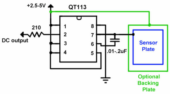
The QT113 is a capacitance touch sensor that does not require AC line voltage to operate. Instead, it detects changes in capacitance caused by the proximity of a user’s body. A sensor plate measuring 2 inches square can sense...