
Two Simple Crystal Test Circuits

The first circuit utilizes a BC548 transistor in a Colpitts oscillator configuration, which is a type of LC oscillator that generates sinusoidal outputs. The oscillator's frequency is primarily determined by the values of the capacitors and the inductor in the circuit, with the crystal acting as a frequency-selective element. The insertion of a crystal allows for precise frequency control, as it introduces a high Q factor into the circuit, leading to stable oscillations. The output from the collector is then processed by the OA91 germanium diode, which rectifies the AC signal into a DC signal. This rectification is crucial for measuring the output oscillation amplitude, which is displayed on a connected meter. The amplitude of the oscillation, indicated by the meter deflection, is directly related to the activity of the crystal; a more active crystal will produce a larger deflection, indicating stronger oscillations.
In the second circuit, another BC548 transistor operates in conjunction with a crystal to form a similar Colpitts oscillator. However, this circuit takes its output from the emitter rather than the collector. This design choice allows for a different output characteristic and is advantageous in certain applications. The output is full-wave rectified, which means that both halves of the AC waveform are utilized, resulting in a more consistent DC output. The small DC bias generated from this rectification process is sufficient to turn on the second BC548 transistor, which is connected to an LED. This LED serves as a visual indicator of the oscillator's activity, lighting up in response to the oscillations produced by the circuit. The interaction between the crystal and the transistors in both circuits exemplifies the principles of oscillation and signal processing in electronic design.In the first circuit, above the BC548 is wired as a colpitts oscillator, the frequency tuned by insertion of a crystal. A good crystal will create high frequency oscillations, the output at the collector is rectified by the germanium OA91 diode and a deflection will appear on the meter.
Thw more active the crystal, the higher the output deflection which may be adjusted with the preset. The next circuit uses a working crystal again used to control the frequency of a colpitts oscillator. This time the output from the oscillator is taken from the emitter and is full wave rectified, the small dc bias will then directly cause the second BC548 to light the LED.
🔗 External reference
Related Circuits
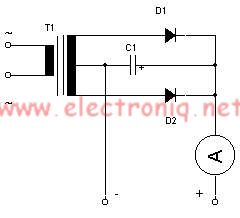
This simple lead-acid battery charger requires a center-tapped transformer (12V 0V 12V) capable of delivering a current of 5 amperes, two diodes, and one capacitor. To charge the batteries, the positive and negative terminals from the charger must be...
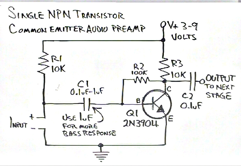
The biasing calculations for collector feedback common emitter amplifiers had not been previously addressed, particularly for a simple one-transistor NPN preamplifier built by Dino. Confusion arose regarding the role of resistor R1 in the schematic, which appeared to serve...
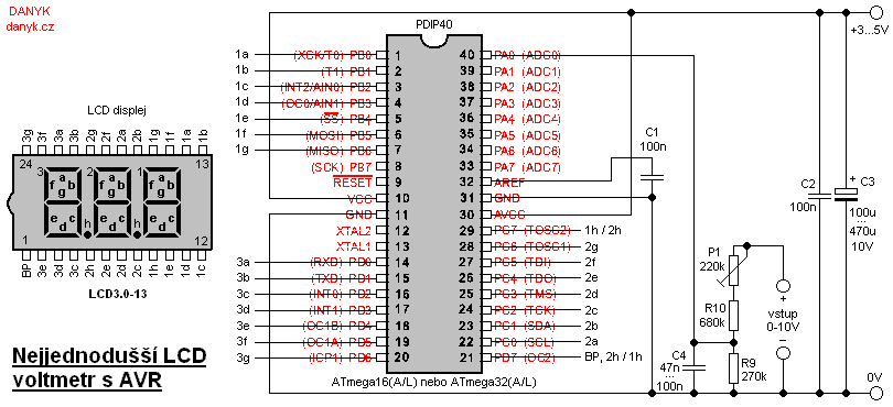
This is likely the simplest digital voltmeter utilizing an Atmel AVR microcontroller and an LCD display. The circuit is managed by a microprocessor IO1 - AVR Atmel ATmega16A, ATmega16L, ATmega16, ATmega32A, or ATmega32. A program is available for free...
Here is the schematic diagram for a very basic crystal radio set without any particular embellishments. This basic old time radio uses no power other than that provided by the transmitting antenna from the radio station. Free power from...
The sound of a wah pedal is characterized by a resonant peak in the signal that can be adjusted. In contrast, a notch represents a sudden decrease in level at a specific frequency, which can be advantageous for achieving...
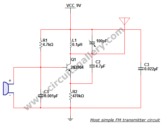
This is the simplest single transistor FM wireless transmitter circuit ever posted in CircuitsGallery. In the field of telecommunications, frequency modulation (FM) transmits information by altering the frequency of a carrier wave based on the message signal. FM utilizes...