
Three water full alarm circuit

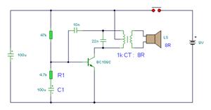
The circuit described is designed to generate an alarm tone through the manipulation of specific component values within the schematic. The components mentioned—Ri, R2, Cl, and C3—play crucial roles in determining the frequency and characteristics of the output sound.
Ri and R2 are resistors that, when adjusted, change the charging and discharging rates of the capacitors Cl and C3. These resistors form a part of an RC (resistor-capacitor) timing circuit, which is fundamental in generating audio frequencies. By varying the resistance values, the time constant of the circuit is altered, leading to different frequencies being produced.
Cl and C3 are capacitors that store and release electrical energy. Their capacitance values directly influence the timing characteristics of the circuit. A higher capacitance value results in a slower discharge rate, which can lower the frequency of the oscillation, while a lower capacitance value increases the frequency. The interaction between these capacitors and the resistors determines the waveform shape and tone of the sound generated.
The KD9300 music integrated circuit serves as the core of the alarm tone generator. This IC is designed to produce various musical tones and can be programmed or configured to generate specific sound outputs based on the input it receives from the RC timing circuit. The KD9300 typically contains internal oscillators and sound synthesis capabilities, allowing for versatile sound generation.
In summary, the alarm tone can be finely tuned by adjusting the resistor and capacitor values, which in turn modifies the RC time constants and affects the oscillation frequency produced by the KD9300. This allows for a range of tones suitable for alarm applications, enhancing the circuit's functionality and adaptability.Change the value Ri, R2, Cl, C3, can change the alarm tone. It uses KD9300 music integrated circuits.
Related Circuits
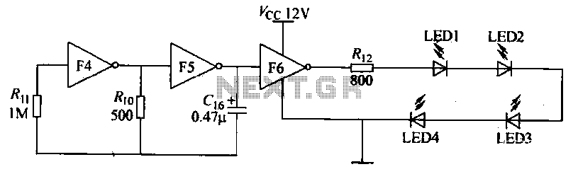
Gates F4, F5, and F6 together form a low-frequency oscillator that drives high-brightness light-emitting diode (LED) flashes. The light-emitting diodes may be arranged around the booth seat for decorative purposes. The automatic referral machine is used prior to operation...
The simple bell circuit without IC. It includes a doorbell circuit that can produce different sounds using integrated circuits, transistors, and resistors. The circuit utilizes a coded trigger mechanism to differentiate between various visitors. When the button is pressed,...

This simple mock flasher LED simulates the indicator of a sophisticated alarm system. It can be placed in doors, gates, and vehicles to confuse intruders. The mock flasher LED circuit is designed to mimic the flashing behavior of a typical...
The following circuit illustrates the circuit diagram of a motor control unit. This circuit is based on the LM317 integrated circuit. Features include diodes that protect the regulator. The motor control unit circuit utilizes the LM317 voltage regulator to provide...
This is a 25-watt basic power amplifier designed for ease of construction at a reasonable cost. It offers superior performance compared to standard STK module amplifiers commonly found in most mass-market stereo receivers produced today. The 25-watt basic power amplifier...
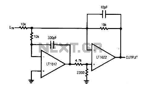
The circuit comprises a low drift LT1012 device and a high-speed amplifier LT1022. It functions as a unity gain inverter, with the summing node located at the junction of three 10k ohm resistors. The circuit monitors the summing node...