
Mock Flasher LED Circuit

The mock flasher LED circuit is designed to mimic the flashing behavior of a typical alarm system indicator light. The primary components of this circuit include a light-emitting diode (LED), a resistor, a capacitor, and a transistor. The LED serves as the visible indicator, while the resistor limits the current flowing through the LED to prevent damage. The capacitor, in conjunction with a resistor, is used to create a time delay, allowing the LED to flash at a predetermined rate.
The circuit operates on a low-voltage DC power supply, typically ranging from 5V to 12V. When powered, the capacitor begins to charge through the resistor. Once the voltage across the capacitor reaches a certain threshold, it triggers the transistor, allowing current to flow through the LED, causing it to illuminate. As the capacitor discharges, the voltage drops, turning off the transistor and extinguishing the LED. This cycle repeats, resulting in a flashing effect.
To enhance the effectiveness of the mock flasher, the flashing rate can be adjusted by changing the values of the resistor and capacitor. A larger capacitor or resistor will result in a slower flashing rate, while smaller values will increase the frequency of the flashes. This flexibility allows for customization to suit various applications, making it suitable for use in different environments, such as residential properties, commercial buildings, and vehicles.
In summary, the mock flasher LED circuit is a simple yet effective solution for simulating an alarm system indicator, providing a practical deterrent against potential intruders.This simple Mock Flasher LED simulates the indicator of a sophisticated Alarm system. It can be placed in doors, gates and vehicles to confuse intruders. T.. 🔗 External reference
Related Circuits
This device is designed for individuals seeking to achieve a tan while minimizing excessive exposure to sunlight. It utilizes electrolytic capacitors as one of its components. The tanning device operates by utilizing a controlled exposure mechanism that regulates the intensity...
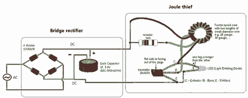
Breathe down and come out on the bright flashlight. In order to promote the voltage, pieces of a highly skilled Joule thief circuit have been used. The Joule thief circuit is a minimalist, low-power boost converter designed to extract energy...

This transverter utilizes the bilateral properties of a balanced mixer to generate a 6-meter output from 2-meter inputs. The component Y1 is a 90-MHz crystal. It is important to note that the input frequency on the 2-meter band is...

The process involves adapting an old phone for Bluetooth functionality, specifically testing the ringer circuit constructed using schematics from Sparkfun. When connecting a section of the schematic to a 3.5V source (Vcc), an output voltage of 45V is observed,...
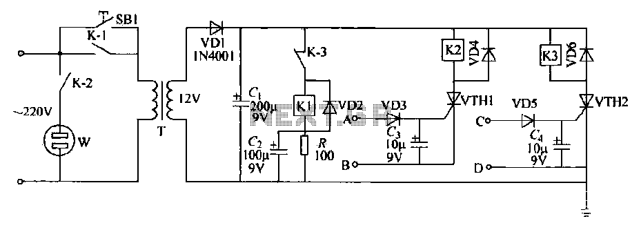
This schematic circuit features two alarm outputs controlled by a timer using thyristors. The system can be turned on or off and will shut down after the power supply is interrupted. It employs a transformer on the primary side...

A real-time clock turns off the counter at night to conserve power. When a bee crosses under the LED, the light is reflected back to the sensor, which is a phototransistor, and triggers a digital input to the Arduino...