
Thyristor Tester

The presented circuit is designed to facilitate the rapid assessment of thyristor devices, specifically Silicon Controlled Rectifiers (SCRs) and triacs. The functionality of the circuit allows for comprehensive testing across all four quadrants of triac operation, which is essential for understanding the behavior of these devices under different electrical conditions.
The schematic typically includes a power supply, a control mechanism (such as a microcontroller or manual switch), and various test points connected to the thyristor being evaluated. The power supply provides the necessary voltage and current levels required for testing, while the control mechanism enables the user to switch between different testing modes.
For SCR testing, the circuit may employ a gate trigger circuit to initiate the conduction state of the SCR. This is crucial for determining the gate sensitivity and the holding current of the device. For triac testing, the circuit should be capable of applying voltage in both polarities and at various phase angles to verify the device's performance in all four quadrants.
In addition, the circuit may feature indicators such as LEDs or a digital display to provide real-time feedback on the operational status of the thyristor being tested. This immediate visual confirmation aids in diagnosing faults or verifying the functionality of the device.
Overall, this thyristor testing circuit is an essential tool for engineers and technicians working with power electronics, ensuring that thyristors are functioning correctly before being integrated into larger circuits or systems.The circuit in the diagram is a very handy tool for rapidly checking all kinds of thyristor (SCR, triac, ). In case of a triac, all four quadrants are te.. 🔗 External reference
Related Circuits
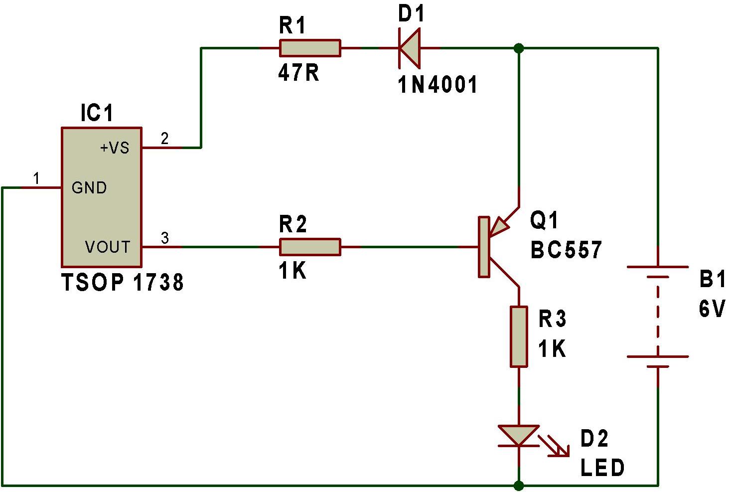
The remote tester circuit operates similarly to a dark sensor using a BC557 transistor. An LDR has been substituted with an IR sensor, specifically the TSOP 1738. The circuit functions as a remote tester; when a remote control switch...
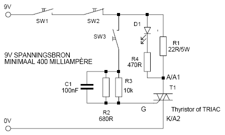
This is a simple but effective thyristor TRIAC tester. Operation at a good thyristor/triac: LED lights when SW3 is pressed. LED turns off when SW2 is pressed. If this occurs, the thyristor/triac is OK. Tip: Hirschmann clips for the...

This is a simple servo tester designed to thoroughly evaluate the capabilities of nearly any modern servo. It features two pushbuttons, labeled CENTRE and SWEEP, along with a potentiometer that functions in the following manner: The servo tester circuit is...
Field-effect transistors (FETs) are integral components found in various applications such as power sections, LCD inverters, uninterruptible power supplies (UPS), amplifiers, monitor B+ circuits, and ATX power supplies. When a FET fails, it is essential to use a meter...
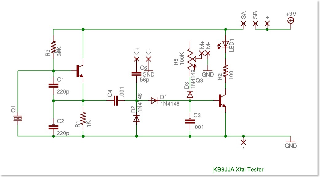
A crystal tester was developed to evaluate various crystals for a project. Existing testers available online were found to be lacking in certain features. Therefore, modifications were made to an existing design to incorporate desired functionalities, along with the...
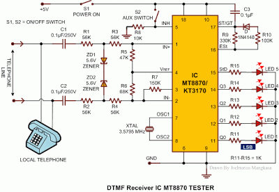
Most telephone equipment today utilizes a DTMF receiver integrated circuit (IC). A widely used DTMF receiver IC is the Motorola MT8870, which consists of 18 pins and is employed in telephones and various other applications. When projects utilizing this...