
Simple Servo Testers

The servo tester circuit is primarily composed of a microcontroller, which processes the input from the pushbuttons and the potentiometer, generating control signals for the servo motor. The CENTRE button is used to position the servo at its neutral point, typically at a 90-degree angle, which is crucial for ensuring that the servo operates correctly during testing. The SWEEP button allows the servo to move through its full range of motion, providing a comprehensive assessment of the servo's responsiveness and range.
The potentiometer is integrated into the circuit to allow for manual adjustment of the servo's position within its operational limits. By turning the potentiometer, the user can set the desired angle, which the microcontroller then translates into a corresponding pulse width modulation (PWM) signal sent to the servo. This signal controls the position of the servo horn accurately, enabling precise testing of the servo's performance.
Power supply considerations are essential for this circuit, as the servo tester should be powered by a stable voltage source compatible with the servo's operating voltage, typically ranging from 4.8V to 6V for most standard servos. Adequate decoupling capacitors should be placed near the power supply pins of the microcontroller to filter out noise and ensure stable operation.
Additionally, the circuit may include LED indicators to provide visual feedback on the operational status of the servo tester. These indicators can signal when the servo is in the center position or when it is actively sweeping, enhancing user experience and usability.
Overall, this simple servo tester serves as an invaluable tool for hobbyists and professionals alike, enabling the efficient evaluation and calibration of servo motors in various applications.This is a simple servo tester which will comprehensively test the capabilities of almost any modern servo. It has two pushbuttons, CENTRE and SWEEP and a potentiometer which works as follows: 🔗 External reference
Related Circuits

This is a simplified version of the Universal Keypad-Operated Switch. The design has been modified to reduce circuit complexity and the number of components required, resulting in somewhat less secure code functionality. However, it remains adequate for many applications....
The circuit presented on this page attempts to be an interface to convert pulses such as provided by a Basic Stamp or R/C receiver to a dual PWM (Pulse Width Modulation) signal required by an H-bridge. The simplest circuit...
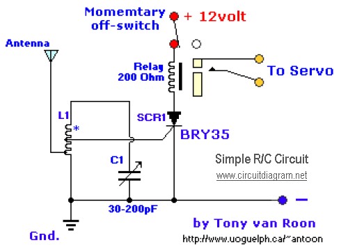
The diagram illustrates a straightforward and efficient receiver designed for activating garage doors, starter motors, alarms, warning systems, and various other applications. The silicon-controlled rectifier (SCR) utilized in this circuit features an exceptionally low trigger current of 30 µA,...

This tester is designed for tracing wiring on Printed Circuit Boards (PCBs). Resistors below 50 ohms function as a short circuit, while those above 100 ohms behave as an open circuit. The circuit comprises a simple multivibrator activated by...
This circuit is a mini bicycle bell. The mini bicycle bell is activated by a switch that functions as a button. When the button is pressed, an electric current flows through a 9V electronic circuit via the transistor Q1....
When a DC voltage signal is transmitted over long distances, it experiences attenuation with unpredictable characteristics introduced by the transmission medium, such as cable resistance that varies with temperature changes. In contrast, carrying information using frequency rather than a...