
Time Delay Relay Circuit with 555

The NE/SE555 integrated circuit is a versatile timer used in various applications, including time delay relays. In this circuit, the IC operates in monostable mode, where it generates a single output pulse in response to an input trigger. The duration of this pulse, which corresponds to the time delay before the relay activates, is determined by an external resistor and capacitor connected to the 555 timer.
To set the time delay, a resistor (R) and a capacitor (C) are selected according to the formula: T = 1.1 * R * C, where T is the time delay in seconds. The resistor can be a variable resistor (potentiometer) to allow for adjustable delays, while the capacitor is typically an electrolytic capacitor to store the charge necessary for timing.
The input trigger can be activated by a momentary switch or a sensor output, providing a low voltage signal to the 555 timer. Upon receiving this trigger, the timer activates the output pin, which in turn energizes the relay coil. This relay can control higher voltage loads, making it suitable for applications such as lighting control, motor activation, or other devices requiring a time delay before activation.
The circuit's design must also consider the power supply voltage, which typically ranges from 4.5V to 15V for the NE/SE555. Proper decoupling capacitors should be placed near the power supply pins of the IC to ensure stable operation and minimize noise. Additionally, if the circuit is expected to operate in varying temperature conditions, the choice of components, particularly the timing capacitor and resistor, should be made with temperature stability in mind to maintain consistent timing performance.
Overall, this time delay relay circuit utilizing the NE/SE555 timer is a reliable solution for applications requiring precise timing control, with the added benefit of temperature stability.This time delay relay circuit is built with IC NE/SE555, produced by Intersil which contains a precision timer. Stability to temperature variations is 0.00.. 🔗 External reference
Related Circuits
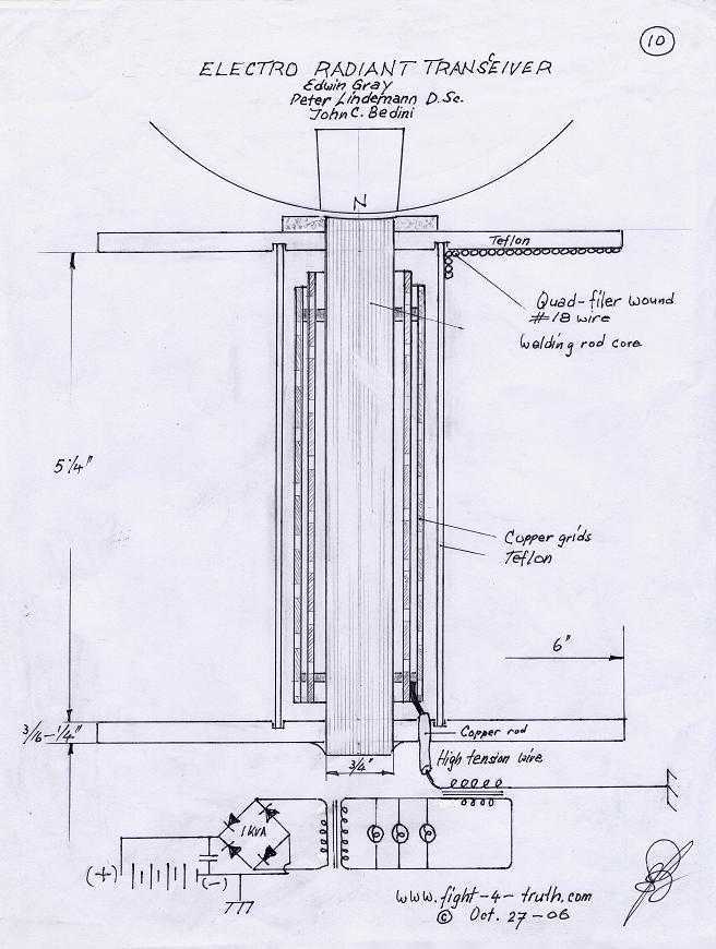
The power is all in the timed switching process. There are two main principles I use of switching the radiant energy the John Bedini way. First, the SG/SSG, Icehouse unidirectional circuit or John Bedini Monopole with the School Girl...
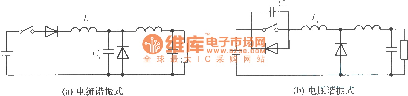
In a commonly used switching stabilized voltage supply, a resonant switch can be utilized to replace the shape of a step-down converter, resulting in a resonant converter circuit. The diagram illustrates the transformation from a step-down converter to a...
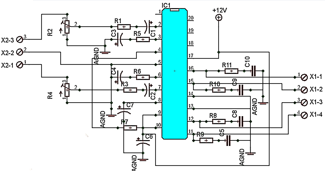
The TA8210AH integrated circuit (IC) is designed for use as an audio power amplifier in car audio systems. Typically, car audio setups include subwoofers and woofers, as the confined space of a vehicle does not require excessively high sound...
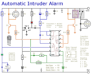
This is a simple single-zone burglar alarm circuit. Its features include automatic exit and entry delays and a timed bell/siren cut-off. It is designed to be used with the usual types of normally-closed input devices such as magnetic reed...
The circuit operates by sending ringing pulses through capacitor C1, resistor R1, and diode D2 to charge capacitor C2 to a voltage of 6V. This voltage causes transistors N1 and N2 to reverse, which activates V1, the analog hook,...
The receiver circuit depicted in the figure requires the insertion of a plug into the radio headphone jack. When the radio receiver detects a signal from the transmitter, an audio signal is output from the jack. This signal is...