
The resonant converter schematic diagram based on step-down circuit (series)
")
The resonant converter circuit offers several advantages over traditional step-down converters, primarily due to its ability to operate at higher efficiencies and lower electromagnetic interference (EMI). In a current resonant converter, the energy transfer is optimized by allowing the inductor and capacitor to resonate at a specific frequency, which minimizes switching losses. This is achieved by controlling the timing of the switch operation to coincide with the zero-voltage switching (ZVS) or zero-current switching (ZCS) conditions, thereby reducing stress on the switching devices and improving overall performance.
In contrast, the voltage resonant converter focuses on maintaining a constant output voltage by utilizing resonant elements to shape the output waveform. This configuration also benefits from reduced switching losses and enhanced efficiency, making it suitable for applications requiring stable voltage regulation.
Both current and voltage resonant converters can be implemented in various applications, including power supplies for telecommunications, industrial equipment, and renewable energy systems. The choice between the two types depends on the specific requirements of the application, such as load characteristics, desired efficiency, and output voltage stability.
The schematic representation of these converters typically includes a switch, resonant inductor, resonant capacitor, and output rectifier. The switch, often a MOSFET or IGBT, is controlled by a pulse-width modulation (PWM) signal that dictates the duty cycle and frequency of operation. The resonant inductor and capacitor form a resonant tank circuit that determines the resonant frequency, which should be tuned to match the switching frequency for optimal performance. The output rectifier converts the resonant AC waveform back into a stable DC output, which can then be filtered to smooth any ripples.
Overall, the resonant converter circuit is a sophisticated solution for modern power supply design, providing enhanced efficiency, reduced EMI, and improved thermal performance compared to traditional step-down converters.In the generalused switching stabilized voltage supply, it can use theresonantswitch to replace the step-down convertor`s shape, and that is the resonant converter circuit. The diagram shows the example of changing step-down convertor to resonant converter: diagram (a) is current resonant ; diagram (b) is voltage resonant..
🔗 External reference
Related Circuits
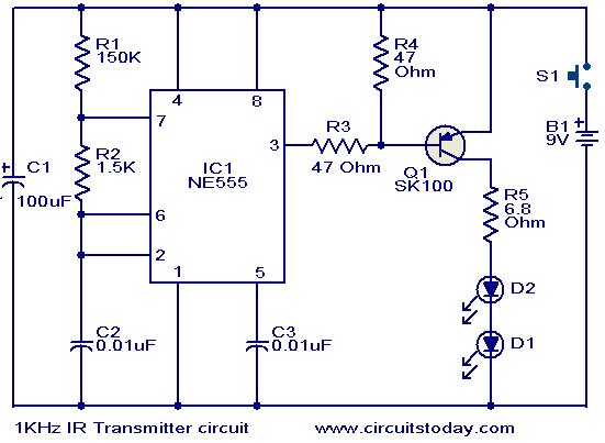
This circuit was designed in response to a request for a 1 kHz infrared (IR) transmitter circuit suitable for remote control applications. It is intended to serve as a low-power IR transmitter with an operating frequency of 1 kHz,...
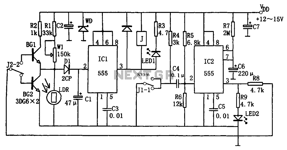
The optical control circuitry for high-performance street lighting is depicted in the figure. The circuit comprises a photoelectric conversion element, specifically a Light Dependent Resistor (LDR), a comparator circuit using an integrated circuit (IC1) which is a 555 timer,...
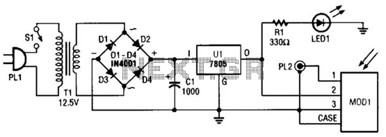
A schematic diagram for the remote analyzer is presented. The circuit is powered by a simple 5-V supply, which includes components such as PL1, SI, Tl, a bridge rectifier formed by diodes D1 through D4, capacitor CI, and a...
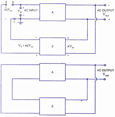
A feedback amplifier with a closed-loop gain, Af, greater than unity can be achieved through the use of positive feedback. This condition also fulfills the phase requirement, leading to the operation of an oscillator circuit. An oscillator circuit generates...
At the beginning of the design process, the designer must determine which circuit structure is appropriate for a specific purpose. During this phase, numerical and symbolic analysis are of limited utility. There are no numerical values available for conventional...
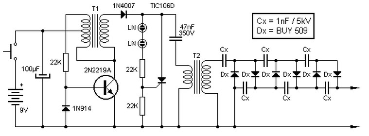
This high voltage source consists of an inverter built around a transistor that generates pulses of 150V. These pulses are supplied to an inverter made of a thyristor and a capacitor, which is connected in series with transformer T2....