
Time-delayed relay

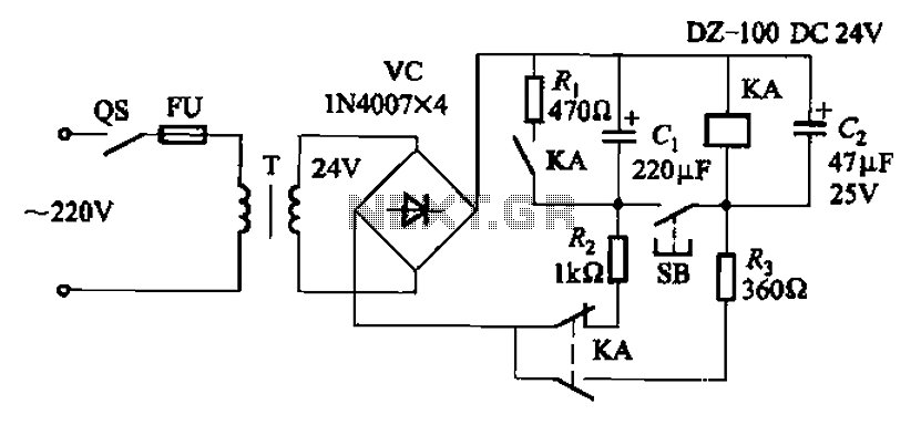
The timing circuit described employs a silicon-controlled rectifier (SCR) as the primary switching element, utilizing a resistor-capacitor (R-C) timing network to establish the desired delay. The timing network consists of resistor R1 and capacitor C1, which work together to create a time constant that governs the delay before the output relay is activated.
Upon powering the circuit, capacitor C1 begins to charge through resistor R1. The time it takes for the capacitor to charge to a specific voltage level, typically the gate trigger voltage of the SCR, determines the duration of the delay. The relationship between the resistance (R1), capacitance (C1), and the voltage across the capacitor can be described by the formula:
\[ t = R1 \times C1 \times \ln\left(\frac{V_{supply}}{V_{supply} - V_{trigger}}\right) \]
where \( t \) is the time delay, \( V_{supply} \) is the supply voltage, and \( V_{trigger} \) is the gate trigger voltage of the SCR.
Once the voltage across C1 reaches the gate trigger threshold of the SCR, the SCR conducts, allowing current to flow through the output relay coil. This energizes the relay, closing its contacts and activating the connected load. The SCR remains in the conducting state until the current through it falls below a certain holding current threshold, at which point it turns off. This characteristic allows for the relay to remain activated for as long as the input power is maintained.
The circuit's design ensures that only a minimal amount of current, measured in microamps, is required to trigger the SCR, which makes it efficient and suitable for applications where low power consumption is critical. Overall, this timing circuit is ideal for applications requiring precise control of output timing, such as in automation systems, delay timers, or sequential control processes.This simple timing circuit can delay an output switching function from 1 seconds to about 1 minute The SCR is triggered by only a few microamps from the timing network Rl-Cl to energize the output relay.
Related Circuits
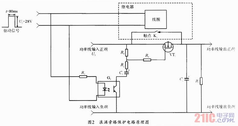
During the power-up of the apparatus, the capacitor is primarily responsible for the emergence of surge current. The schematic diagram of the principle is illustrated in Fig. 1. After K1 closes, the capacitor begins to charge, assuming that the...
This toggle circuit utilizes two 555 timers configured as inverters. Pins 2 and 6 serve as the threshold and trigger inputs for the first timer, while pin 5 provides the output. The output at pin 5 will consistently reflect...
This device can be interfaced with various adapters, including a keypad adapter (optional), an RF receiver (optional), or via the internet (optional). It can also be adapted to operate with other external attachments. The device features multiple interfacing options, enhancing...
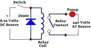
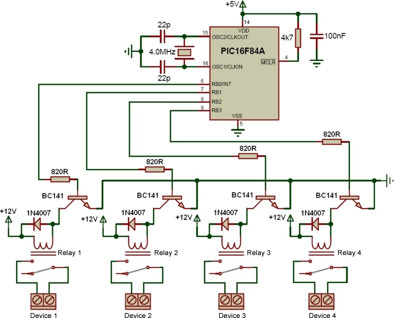
A relay is an isolated switch, with no direct connection between the switching device and the load. Relays are commonly used to control high-voltage devices, protecting sensitive low-voltage components from damage. Various types of relays exist, but electromechanical relays...
The transformer is a 220V to 12V, 50Hz, and 3.6VA PCB type transformer. The model depicted is HRDiemen E3814056. Being encapsulated, it is isolated from external influences. A 250V 400mA glass fuse protects the circuit from damage caused by...
After the turn-off circuit is first applied to the next KA KA, the intermediate interval required is less than Is. This is due to the time needed, which is equal to three times the charge time constant of the...