
Single-button control off of the relay circuit 2

In this circuit description, the focus is on the turn-off behavior of a specific electronic circuit that includes a capacitor (C1) and resistors (R2). The charge time constant, denoted as τ (tau), is critical for determining how quickly the capacitor can charge to a specified voltage. The time constant τ is defined as τ = R * C, where R is the resistance and C is the capacitance.
In this case, the expression t = 3r2R2C1 indicates that the time required for the capacitor to charge is three times the product of the resistance (r2) and the capacitance (C1). This implies that the circuit has a relatively slow response time, which is typical for RC (resistor-capacitor) circuits.
As the circuit operates, after the turn-off condition is applied, the capacitor C1 begins to charge. The voltage across C1 is monitored, and it is noted that after 66 seconds, the voltage exceeds 20V. This behavior suggests that the circuit is designed to operate within specific voltage and time parameters, likely for applications such as timing circuits, voltage regulation, or energy storage.
The design considerations for such a circuit would include selecting appropriate values for the resistors and capacitors to achieve the desired charge time and voltage levels. Additionally, the components must be rated for the voltage and current levels expected during operation to ensure reliability and safety.
Overall, the performance of the turn-off circuit is closely linked to the chosen components and their arrangement, affecting the charging and discharging characteristics of the capacitor, which are crucial for the intended application.After the turn-off circuit is first applied to the next KA KA, intermediate interval required less than Is, this is because when the time is up to 3 times the charge time const ant r C1, i.e. t 3r 2R2C1 3 1 l03 X 220x lO- s a o. When the 66s, Cl both ends of the capacitor voltage to rise above 20V.
Related Circuits
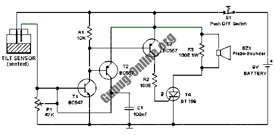
This design features a simple circuit for a tilt sensor alarm that can be constructed using readily available and inexpensive components. The circuit is based entirely on transistor technology. The homemade tilt sensor for this circuit utilizes a standard...

The automatic emergency light circuit has the following features: 1. When the mains supply (230V AC) is available, it charges a 12V battery up to 13.5V, after which the battery is disconnected from the charging section. 2. When the...
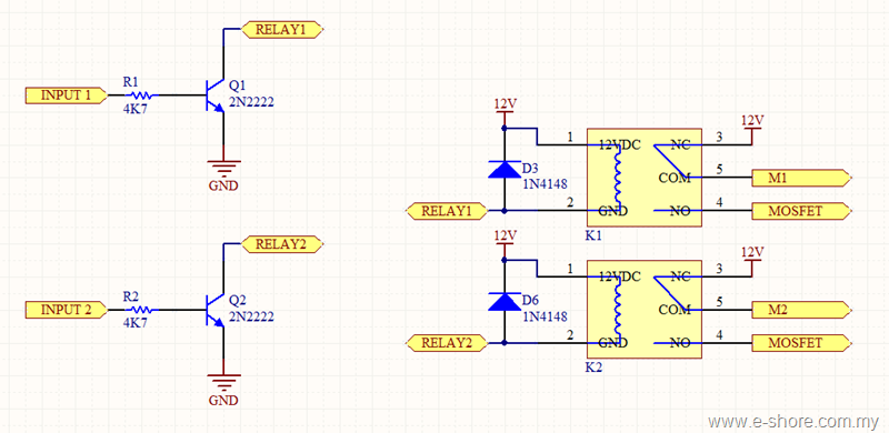
The circuit utilizes two sets of relays for each motor to switch the motor's direction, and one set of MOSFETs for each motor to control the motor's speed. The MOSFET and relay circuit will be divided into three parts...
The simplest method of detecting metal is through a beat frequency oscillator. The circuit consists of two balanced oscillators: one serves as the detector element while the other provides a reference signal. The reference oscillator frequency is set to...
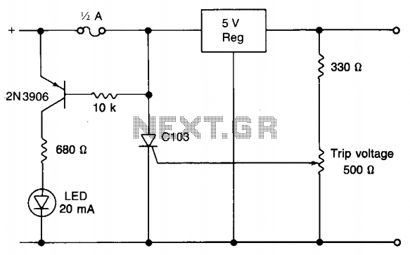
When utilizing a regulated power supply to decrease voltage, there exists a risk of component failure within the supply, potentially resulting in damage to connected equipment. While a fuse can provide protection against excessive current draw, it may not...
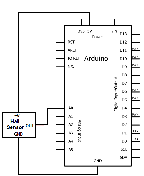
The Hall effect sensor utilized in this circuit is the A1302 Hall effect sensor manufactured by Allegro. This integrated circuit (IC) is capable of detecting magnetic fields. It will be connected to an Arduino, allowing the Arduino to read...