
Time relay three-start circuit

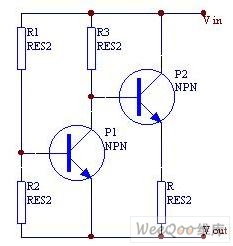
The circuit design utilizes a series of relays to facilitate the gradual increase in motor speed. The three relay contacts serve to control the engagement and disengagement of different resistance levels in the rotor circuit. Initially, the motor operates with a higher resistance, which limits the current flow and consequently the speed of the motor.
As the motor begins to operate, the first relay is activated, which reduces the resistance in the rotor circuit, allowing more current to flow. This increase in current results in a corresponding increase in motor speed. The second relay further decreases the resistance, and the process continues until the third relay is activated.
At this final stage, the rotor winding variable resistor is effectively shorted out, allowing maximum current to flow through the motor windings. This configuration ensures that the motor accelerates smoothly and reaches its rated speed without abrupt changes that could potentially damage the motor or connected components.
The automatic removal of resistance levels is crucial for protecting the motor during startup, as it prevents excessive current draw that could lead to overheating or burnout. The use of complementary operation in the relays ensures that the transition between different resistance levels is seamless, maintaining a stable and controlled acceleration profile for the motor.
Overall, this circuit is an effective solution for applications requiring precise control over electric motor speed, combining reliability and efficiency through its relay-based design. Circuit shown in Figure 3-159. The circuit uses complement each other three times and three relay contacts, followed by the automatic removal of the rotor circuit resistance le vels, and finally the rotor winding variable resistor is reduced to zero (all short), so that the electric motor speed gradually increased, and finally reach the rated speed.
Related Circuits
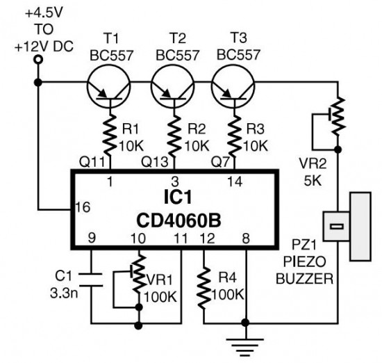
The circuit generates pulses of 1.25 Hz from pin 1 and 20 Hz from pin 14. The three output pins of IC1 are connected to the base terminals of transistors T1, T2, and T3 through resistors R1, R2, and...
The most extreme option would be to supply power through a battery pack. A more plausible source would be the car's battery. However, since the objective of the circuit is to activate the buzzer when the headlights are on,...
When the current is below the specified threshold, the bias current supplied by resistor R1 causes transistor P3 to saturate and conduct. In this state, it is unable to regulate the current effectively. Conversely, when the current reaches or...

The PM4040F is utilized in switching power supply applications for medium power ranges. It is designed to drive power supplies between 200W and 800W, as illustrated in the accompanying bridge circuit. For power applications below 1000W, an alternative circuit...

Timers are widely used in industrial and domestic applications for automating tasks. Microcontrollers can be used to design versatile and accurate timers. Timers play a crucial role in both industrial and domestic environments by facilitating the automation of various tasks....
This UHF transmitter is designed for low power applications such as remote controls for garage doors, operating systems, and wireless alarms. This UHF FM transmitter is equipped with... This UHF transmitter operates within the Ultra High Frequency (UHF) band, which...