
phone ringtone generator circuit

The described circuit utilizes an integrated circuit (IC1) to produce two distinct pulse frequencies: 1.25 Hz and 20 Hz. The output from pin 1 provides a low-frequency pulse signal, while pin 14 delivers a higher frequency pulse signal. The connection of the output pins to the base of transistors T1, T2, and T3 through resistors R1, R2, and R3 allows for the control of these transistors, which act as switches to modulate the piezo buzzer's operation.
The piezo buzzer, which is designed to operate at approximately 1 kHz, is integral to generating audible sound. Transistor T3 plays a crucial role in the modulation of the buzzer's sound output. By turning the buzzer on and off at a frequency of 20 Hz, a ringing tone is produced, which is characteristic of a typical ringtone. The operation of T3 allows for the creation of a pulse train where the buzzer is activated for 0.4 seconds, followed by a brief pause before reactivating for another 0.4 seconds. The subsequent two-second interval of silence provides a clear distinction between the sound pulses, enhancing the auditory recognition of the ringtone.
This circuit exemplifies the use of basic electronic components, including transistors and resistors, to create a functional sound-generating device. The automatic repetition of the pulse pattern ensures continuous operation, making it suitable for applications such as alert signals or notification tones in various electronic devices.At the same time, pulses obtainable from pin 1 will be of 1. 25 Hz and 20 Hz at pin 14. The three output pins of IC1 are connected to base terminals of transistors T1, T2, and T3 through resistors R1, R2, and R3, respectively. Working with a built-in oscillator-type piezobuzzer generates about 1kHz tone. In this particular circuit, the piezo-buzzer is turned on` and off` at 20 Hz for ring tone sound by transistor T3. 20Hz pulses are obtainable at the collector of transistor T3 for 0. 4-second duration. Just after a time interval of 0. 4 second, 20Hz pulses become again obtainable for another 0. 4-second duration. This is followed by two seconds of nosound interval. Thereafter the pulse pattern repeats by itself. 🔗 External reference
Related Circuits
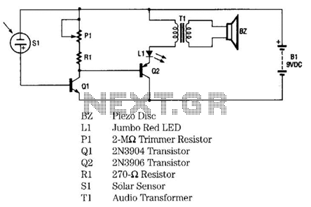
The infrared remote-control tester employs a sensitive PN-type solar sensor directly connected to a Darlington amplifier composed of transistors Q1 and Q2. Biasing is achieved through resistor R1 and PI, a variable resistor that functions as a sensitivity control....
The EQ-2 is a 6-band graphic equalizer circuit. Each band is controlled by potentiometers RV1-6, which are designed as faders for improved visual indication of adjustments. However, standard potentiometers can also be used as replacements. At the center position...
Incremental rotation or linear encoders are widely used, but they typically do not provide a direction signal. This design presents a straightforward method to detect forward or reverse direction. Incremental encoders usually generate two output signals, referred to as...
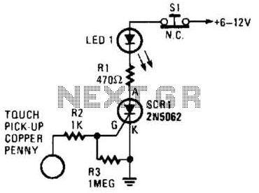
When the touch-on contacts are bridged, pin 6 of U1 goes low, which forces its output (the set output) at pin 4 to go high. That high divides along two paths; in one path, the output is applied to...
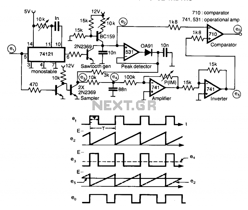
A circuit designed to multiply the width of incoming pulses by a factor that can be greater or less than unity is straightforward to construct. It features a single adjustable potentiometer for selecting the multiplying factor. This factor is...
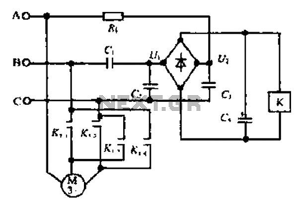
Composition ratio circuit. The circuit consists of resistors and capacitors that form a shift register circuit with diodes VD1 to VD4, creating a bridge for electric current. Capacitor C4 is utilized for filtering applications and for eliminating instantaneous relay...