
Timely Beeper

The timer circuit is constructed around the widely used binary counter IC CD4060, which resets through capacitor C2 and resistor R2 upon power-on and begins oscillating with components C3 and R3. The CD4060 functions as an oscillator, binary counter, and frequency divider. Its internal oscillator, based on three inverters, generates a basic frequency determined by the capacitor connected to pin 9 and the resistor at pin 10. Each output transitions high upon completing the timing cycle. To extend the maximum timing period, output Q10 is omitted within the IC, allowing for double the time between outputs Q9 and Q11. The IC contains an oscillator and 14 series-connected bistables in a ripple cascade arrangement. The oscillator signal is fed to the first bistable, which in turn drives the second bistable, and so forth. Each bistable divides its input signal by two, resulting in a total of fifteen signals, each at half the frequency of the preceding signal. Ten of these signals are available at output pins Q3 to Q13. In the circuit, an LED is connected to the first output Q3, causing it to blink every 4 seconds. After approximately 30-37 minutes, pin 2 (Q12) goes high, triggering the buzzer to beep. This beeping continues for 30 minutes, drawing attention to the need to switch off the load. The circuit should be housed in a small plastic enclosure and mounted inside the switchboard. Power can be sourced from the phase and neutral contacts of the plug to which the load is connected, ensuring that both the load and the beeper circuit receive power when the plug switch is activated. The CD4060 provides sufficient output voltage and current to drive LEDs and low-voltage buzzers, resulting in bright LED illumination and loud buzzer sounds. The 33 kΩ resistor may become slightly warm; if it overheats (check only after disconnecting from AC lines), a 2-watt resistor should be used instead. Since the circuit activates only with the load, it minimizes potential issues.
Caution: The circuit is directly connected to high-voltage AC and lacks galvanic isolation from the hot line, posing a risk of electric shock if handled improperly. Avoid touching or troubleshooting the circuit while it is connected to the mains.Fix this circuit in the switch board that provides power to the loads such as Water heater, Electric Iron etc to remind you that the load is switched on. LED blinks indicating the load on status and the buzzer beeps every 30 minutes. This helps to prevent the wastage of energy usually happens when we forget to switch off these devices.
Thi s can be also used to remind, if remote lights such a terrace light is switched on unnoticed. To make the circuit a compact one to enclose inside the switch board, a Resistor based transformerless power supply is used. The 1 watt 33 K resistor reduces the high volt AC to low volt AC which is rectified by the full wave rectifier comprising D1 through D4.
Rectified DC is made ripple free by C1so that around 9 volts DC will be available to power the circuit. CD 4060 works safely between 5-18 volts DC and the rectified DC to IC1 is less than 9 volts in normal condition and will not destroy the device unless resistor R1 fails.
The timer circuit is built around the popular binary counter IC CD4060 which resets through C2and R2 at power on and starts oscillating with the components C3 and R3. IC 4060 is an Oscillatorcum binary counter cum frequency divider. Its inbuilt oscillator is based on three inverters. The basic frequency of the internal oscillator is determined by the value of the capacitor connected to its pin 9 and that of the resistor in its pin 10.
Each output goes high after the completion of the timing cycle. To get maximum time period output Q10 is omitted in the IC itself so that double time is available between Q9 and Q11. Inside the IC there is an oscillator and 14 seriesconnected bistables (Ripple cascade arrangement). Internally the oscillator signal is applied to the first bistable which drives the second bistable and so on.
Since each bistable divides its input signal by two, a total of fifteen signals are available, each of half the frequency of the previous one. Ten of these fifteen signals are available on the output pins Q3- Q13. In the circuit LED is connected to the first output Q3 so that it blinks at an interval of 4 seconds.
After 30- 37 minutes (slightly affects if the input voltage drops) Pin 2 (Q12) turns high and buzzer beeps. Beep continues for 30 minutes so that, we will get attention to switch off the load. Enclose the circuit in a small plastic case and fix it inside the switch board. Power can be tapped from the Phase and Neutral contacts of the Plug to which the load is connected. So that when the plug switch is turned on, both the load and the beeper circuit gets power. CD 4060 gives sufficient output voltage and current to drive LEDs and low volt buzzers. So the brightness of LED will be high and beeps from the buzzer will be loud. 33 K resistor will heat up slightly and if the heat is too high (check only after removing from AC lines) use 2 watt resistor.
Since the circuit turns on only along with the load, it will not cause much problems. Caution: The circuit is connected to the high volt AC directly and there is no galvanic isolation between the hot line and the circuit. So there is risk of Shock if handled carelessly. Do not touch or trouble shoot the circuit when it is connected to mains. 🔗 External reference
Related Circuits
This circuit is designed for alerting purposes after a specific duration has elapsed. It is suitable for table games that require a fixed time to answer a question or move a piece, serving as a modern substitute for an...

When the light on the answering machine blinks, the resistance of photoresistor Rl increases, triggering the timer (U1) and generating a 0.2-second pulse that activates BZ1. Rl is optically coupled to the LED on the answering machine and is...
This schematic illustrates a beeper circuit designed to produce a continuous beep sound while simultaneously flashing an LED. The beeper circuit typically consists of a few key components: a sound-generating device (such as a piezo buzzer), an LED for visual...
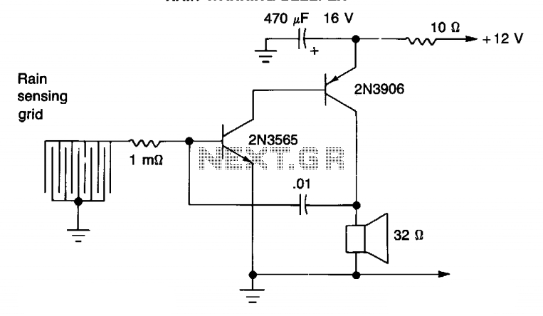
A single drop of rain on the sensing pad of this bleeper initiates an audio warning. Additionally, it can be activated by rising water levels. The circuit incorporates two transistors and features feedback through capacitor C1; however, transistor Tr1...
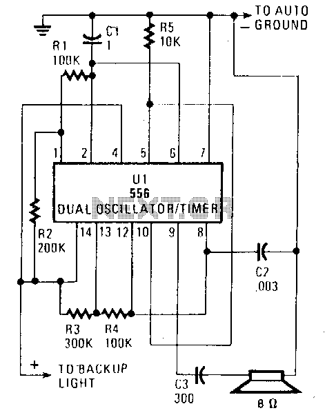
When the vehicle is placed in reverse, the circuit emits a loud beep at a frequency of approximately one beep per second (1Hz). Half of the U1 component, a 556 dual oscillator/timer, functions as a slow-pulse oscillator with a...
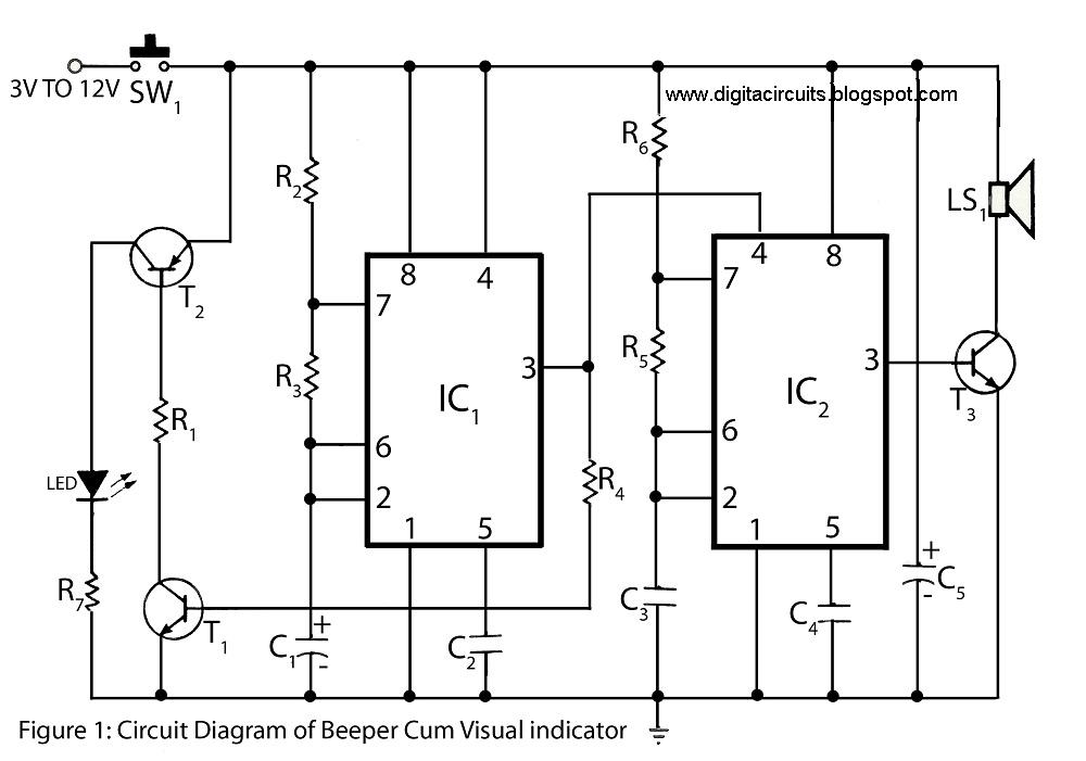
This circuit of a beeper and visual indicator is constructed using two timer integrated circuits (ICs) configured in an astable multivibrator mode. The frequency produced by IC1 is regulated by capacitor C1. The output from pin 3 of IC1...