
Timer

The tanning timer circuit is designed to provide a controlled exposure to sunlight, utilizing a rotary switch to select from six different settings tailored for various skin types, often referred to as Photo-types. Each setting corresponds to a specific maximum exposure time, which is crucial for preventing skin damage. The rotary switch can be implemented using a multi-position rotary switch that connects to a resistor network or a microcontroller with predefined time values for each position.
A key component in this circuit is the photoresistor (LDR), which serves as a light sensor. The photoresistor's resistance decreases with increasing light intensity, allowing it to dynamically adjust the preset timer based on the current sunlight brightness. This functionality ensures that the timer compensates for varying environmental conditions, extending the exposure time when sunlight is less intense and reducing it when brightness increases. The integration of the photoresistor into the circuit can be achieved through an analog input to a microcontroller or by using a comparator circuit that adjusts the timing based on the resistance value.
Once the preset time elapses, the circuit activates a beeper that emits an intermittent sound, signaling the end of the tanning session. The beeper can be a simple piezoelectric buzzer or a more complex audio output device, depending on the desired sound quality and volume. To ensure the user can silence the beeper, a switch (SW2) is included, which, when activated, completely disconnects power from the circuit, effectively stopping all operations. This switch should be designed for easy access, allowing the user to quickly turn off the circuit without fumbling.
The overall circuit can be powered by a battery or an external power supply, with appropriate voltage regulation to ensure the components operate within their specified limits. Additional features may include an LED indicator to show when the timer is active and a power-saving mode to extend battery life when the device is not in use. Proper PCB layout and component selection are essential to ensure reliability and safety in outdoor conditions.This timer was designed for people wanting to get tanned but at the same time wishing to avoid an excessive exposure to sunlight. A Rotary Switch sets the timer according to six classified Photo-types . A Photo resistor extends the preset time value according to sunlight brightness (see table). When preset time ends, the beeper emits an intermittent signal and, to stop it, a complete switch-off of the circuit via SW2 is necessary. * Needing only o 🔗 External reference
Related Circuits
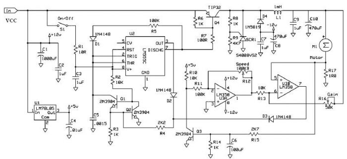
Speed regulation is achieved by monitoring the motor current with resistor R17 and utilizing it as positive feedback to offset motor resistance losses. The gain potentiometer should be adjusted to just below the threshold where motor speed begins to...
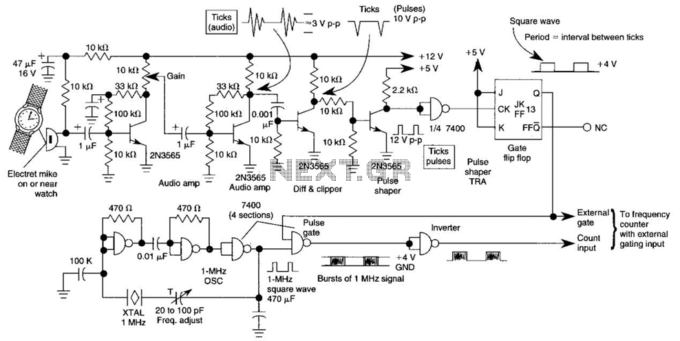
This circuit adapts a frequency counter to measure intervals. It was originally utilized as a shutter speed checker for photographic applications. The watch ticks are clipped, shaped, and formed into a square wave. This square wave is employed to...
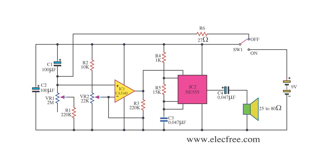
This circuit sets the time using a simple model that can accurately maintain the time over extended periods. It employs the CA3140 integrated circuit for its functionality. The circuit utilizes the CA3140 operational amplifier, which is known for its high...
200W Lamp Flasher is used to flash lamps, bulbs and halogen lamp to give your product that attracting look. More: Input supply - 6 ~ 12 VDC Output - upto 200 W lamp / bulb load Optically isolated Mains supply Onboard preset...
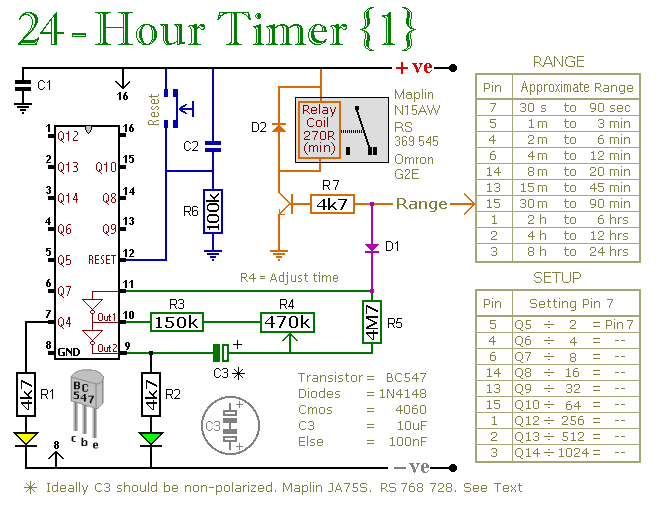
A pair of multi-range timers that provide timing periods extending up to 24 hours and beyond. Both timers are fundamentally identical, with the primary distinction being their relay behavior upon the completion of the timing cycle. Version 1 activates...
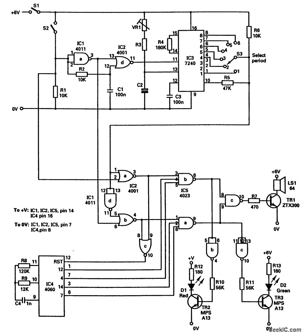
This circuit utilizes the 7240 CMOS programmable timer chip (IC3), which has an accuracy of 0.5 percent. It features a time-base generator, with the frequency determined by a resistor and a capacitor. The basic time period is RC seconds;...