
Two Cmos Based 24-Hour Timers circuit

These multi-range timers are designed to accommodate a variety of applications where precise timing control is essential. Each timer can be set to run for durations ranging from seconds to 24 hours, making them versatile for both short-term and long-term timing requirements.
In Version 1, the relay is energized upon the completion of the set time, which can be particularly useful in applications where an action needs to be triggered at the end of the timing period, such as activating a motor or turning on a light. This configuration is advantageous for applications requiring immediate action upon timer expiration.
Conversely, Version 2's de-energizing relay upon time completion is suitable for applications where it is necessary to turn off devices or systems after a designated period. This design is particularly beneficial in energy-saving scenarios, as it minimizes power consumption once the timing cycle is completed.
Both versions utilize an efficient timing circuit that can be implemented using various electronic components such as resistors, capacitors, and a microcontroller or timer IC. The choice of components will depend on the desired accuracy and reliability of the timing function.
The power consumption characteristics of each version are crucial for applications where energy efficiency is a priority. Version 1's lower power usage during operation makes it ideal for applications where the timer is frequently active, while Version 2's reduced power consumption after the timer stops is more suitable for infrequent or intermittent use.
In summary, the selection between Version 1 and Version 2 should be guided by the specific functional requirements of the application, considering factors such as the need for relay activation or deactivation, energy efficiency during operation and post-operation, and the duration of the timing cycle required.A pair of multi-range timers offering periods of up to 24 hours and beyond. Both are essentially the same. The main difference is, that when the time runs out, Version 1 energizes the relay and Version 2 de-energizes it. The first uses less power while the timer is running; and the second uses less power after the timer stops.
Pick the one that best suits your application.. 🔗 External reference
Related Circuits
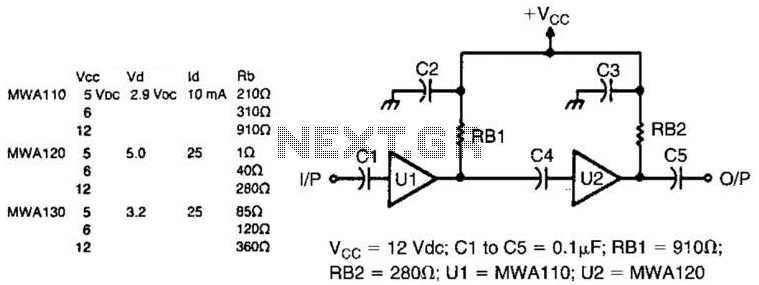
Motorola MWA 110, 120, or 130 are wideband amplifier ICs. This wideband preamp circuit can be used in many applications. Keep the leads short when constructing the circuitry. PC board layout (shading represents copper) and parts layout. X is...

Electronic FM Telephone Transmitter Schematic. The following schematic design illustrates a circuit diagram for an FM telephone transmitter built on a compact PC board layout. This small design allows it to be easily integrated within the housing of a...
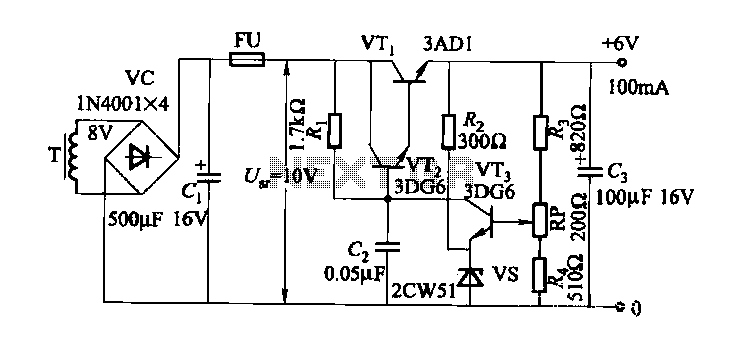
A composite pipe can be reduced to facilitate the adjustment of the control current within the tube. Composite pipes are often utilized in various applications due to their lightweight, strength, and flexibility. When discussing the reduction of a composite pipe,...
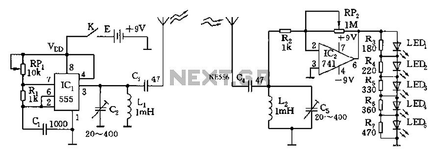
The circuit diagram of the device features a 555 timer IC configured as a transmitter and a receiver, divided into two sections. The 555 timer in the transmitter section serves as the core component of a frequency oscillator. The...
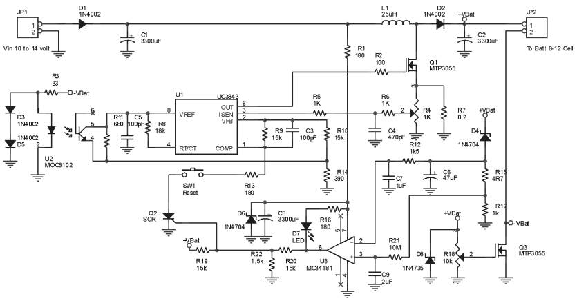
The Ultra Fast Battery Charger for Nickel-Cadmium (NiCad) battery cells is designed to efficiently charge NiCad batteries. This charger, referred to as the Ultra Fast NiCad Battery Charger, is capable of rapidly filling NiCad battery cells. The charger is...

This design outlines a simple wideband output amplifier suitable for use as a 50-ohm transmission line driver. The circuit is constructed using the CA3140 operational amplifier. When utilized alongside the function generator and sine wave shaper circuits, it delivers...