
Tiny Tuned Loop Antennas

The antenna's operation in transmit mode is analogous to its operation in the receive mode. In receive mode, the quality of the receiving antenna directly influences the amplitude of the signal across it, which is affected by multiple factors. Understanding the relationship between these factors can aid in optimizing the design for specific applications. The formula that relates these factors indicates that as the carrier frequency increases, the number of turns on the antenna increases, the antenna's Q factor rises, the diameter of the antenna increases, and the strength of the RF magnetic field received by the antenna also increases. This leads to a larger output signal, which corresponds to greater sensitivity in the antenna's performance.
In terms of circuit design, a typical resonant loop antenna circuit consists of an inductor (the coil) and a capacitor connected in parallel. The inductor's inductance (L) and the capacitor's capacitance (C) determine the resonant frequency (f) of the circuit, which can be calculated using the formula:
\[ f = \frac{1}{2\pi\sqrt{LC}} \]
Where:
- \( f \) is the resonant frequency in Hertz (Hz),
- \( L \) is the inductance in Henries (H),
- \( C \) is the capacitance in Farads (F).
The choice of wire gauge for the coil and the number of turns will impact the quality factor (Q) of the antenna, which is a measure of its efficiency. A higher Q indicates a narrower bandwidth and better selectivity, which is desirable for receiving specific frequencies. The physical layout of the antenna, including its diameter and height above ground, will also influence its radiation pattern and impedance, which should be matched to the receiver for optimal performance.
In summary, the design of a resonant loop antenna involves careful consideration of coil dimensions, inductance, capacitance, and the relationship between these parameters to ensure effective operation in both transmit and receive modes.Loop Antennas are considered to be "samall" when their diameter drops below about 1/10 of the wavelength they are intended to be used at. In this case, I use the term "Tiny" because the antenna's diameter is about 1/30,000 the wavelength, and at 5.5 cm in diameter, they are quite small in human terms.
Coils are one of the few components experimenters can easily do a good job of making for themselves, and the coil, with or without the core, is the major component in a resonant loop antenna. The resonant loop antenna is fundamentally a parallel resonant LC circuit tuned to the carrier frequency.
A coil, or in some cases coils, of wire form the antenna, which is usually mostly inductive, and a parallel capacitance is used to make the antenna resonant at the desired frequency. Time varying magnetic fields from the signal source that cross the coils of wire induce current in the loop, which results in a voltage across the output.
The closer the incoming signal is to the loop's resonant frequency, the higher the output voltage. There are several formulae available for calculating the number of turns to use in a coil once you decide how much space you have for it, but I haven't found one that seems to get close enough to use without trimming. To get a loop of the desired inductance, I wind a coil of about the number of turns I expect to need, and then measure it.
Since inductance is proportional to the square of the number of turns in a coil, I calculate an inductance factor for that size coil, and then I use that inductance factor to calculate the number of turns I will need. If I am careful, this goes pretty quickly with only a couple of iterations before the inductance is close enough to work with.
The antenna's operation in transmit mode is analogous to its operation in the receive mode, so let's take the receive mode first. The better the receiving antenna, the larger the signal appearing across it, and a lot of factors affect the amplitude.
Looking at how these factors relate to one another (See Formula 1) can be useful in understanding how to optimize the design for a particular application. At first glance the formula may look a little intimidating, but all it really means is that the higher the carrier frequency, the more turns on the antenna, the higher the antenna's Q, the larger the antenna's diameter, and the stronger the RF magnetic field received by the antenna, the larger the signal at its output - larger signals on the output correspond to greater sensitivity.
🔗 External reference
Related Circuits
I have no idea whether the RCA 40468A FET is still available or not. It came in a 4 pin metal can - with the 4th pin connected to the substrate. I have successfully substituted other N-channel devices, such...
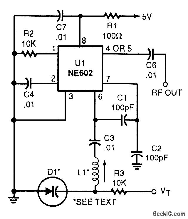
This voltage-tuned Clapp oscillator utilizes a varactor diode to determine its operating frequency. The diode used is an NTE614, and the inductor L1 has a value of approximately 7 microhenries. With this configuration, the oscillator can operate within a...
All ATL-3 loop windings are center-tapped and balanced with respect to their amplifier/receiver chassis ground, which leads to self-cancellation of electric field interference. Magnetic noise fields, such as those from televisions and electric meter boxes, or electromagnetically radiated interferences,...
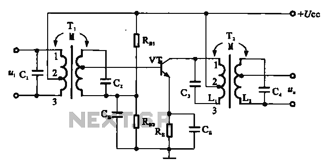
There are two resonant circuits in a double-tuned amplifier circuit, which consists of transformers T1 and T2 with primary and secondary coils that include parallel resonance capacitors. This circuit exhibits a resonance function and can be classified based on...
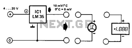
An effective temperature sensor circuit is designed to receive power from a 4-to-20 mA loop without impacting the loop current. The temperature sensor integrated circuit (IC) used is the AD590F, which operates with a supply voltage ranging from 4...
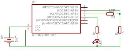
When first discovering this article, it was noted that it is a great project utilizing only a few components. Microcontroller projects based on LEDs are of particular interest. This project is very simple and worth trying. It is inspired...