
A double-tuned amplifier circuit

The double-tuned amplifier circuit is a specialized electronic configuration that enhances signal amplification by utilizing two resonant circuits. Each resonant circuit is designed to resonate at a specific frequency, allowing for improved selectivity and gain at that frequency. The transformers T1 and T2 serve as the core components of this configuration, with their primary and secondary coils strategically arranged to achieve the desired coupling effect.
The mutual coupling configuration, as depicted in Figure (a), relies on the magnetic interaction between the inductors. By adjusting the physical separation between inductors L1 and L2, the mutual inductance can be varied, thereby influencing the overall coupling coefficient. This adjustment enables fine-tuning of the amplifier's frequency response, allowing it to selectively amplify signals at the resonant frequency while attenuating others. The use of capacitors, such as C3, in conjunction with the inductors further refines the tuning process, ensuring that the amplifier operates efficiently within its intended frequency range.
On the other hand, the capacitive coupling configuration illustrated in Figure (b) employs an external capacitor, Ck, to control the coupling between the two tuners. This method allows for a more flexible tuning process, as the degree of capacitive coupling can be altered without physically moving the inductors. By adjusting the capacitance, the amplifier can be optimized for different signal frequencies, making it versatile for various applications.
Overall, the double-tuned amplifier circuit is an essential component in radio frequency (RF) applications, where precision and selectivity are crucial. Its design facilitates enhanced performance in communication systems, audio processing, and other electronic devices that require reliable signal amplification.There are two resonant circuits tuned amplifying circuit known as a double tuned amplifier circuit, i.e. the transformer Ti, T2 of the primary and secondary coils are provided has parallel resonance capacitor
has a resonance function. Depending on the coupling can be divided into two mutual coupling and capacitive coupling type Peng, Figure 3-20 below. Figure (a) shows the mutual inductance coupling double tuned amplifier which is tuned amplifier with the single exception that use Ll, C3 tuned circuit tuned circuit in place of a single secondary winding.
Using mutual coupling between the tough, secondary, or core that is changing the distance between the position of Li and Li can change their degree of coupling. Figure (b) shows the level of capacitive coupling amplifier tuned by changing an external capacitor Ck two tuners back road between the degree of coupling.
Related Circuits
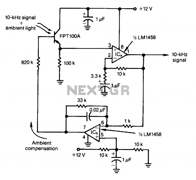
The feedback control of the phototransistor in this optical detector helps negate the effects of varying ambient light sources. The output of a modulated visible-light LED is detected, amplified, buffered, and fed through a low-pass filter. Ambient light signals...
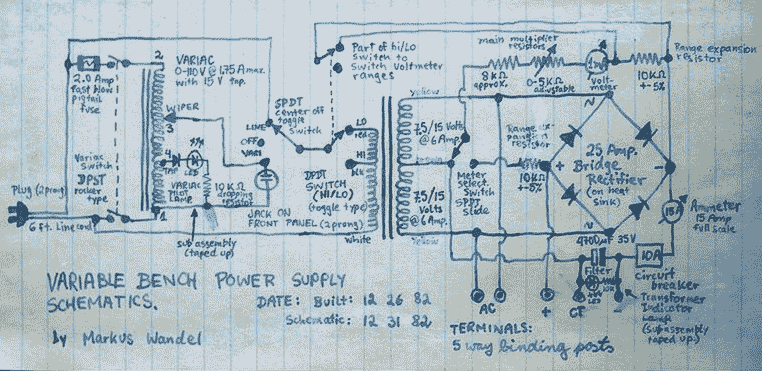
This power supply is able to deliver adjustable center-tapped DC from 0 to about 30 volts, as well as AC directly from the Variac and from the main transformer before the rectifier. What's primitive by today's standard is that...
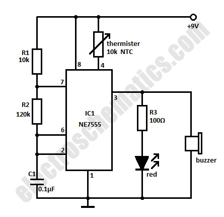
The high-temperature alarm will emit a beep and the LED will blink when the temperature of the device rises abnormally. This simple overheating alarm is designed to monitor heat levels. The high-temperature alarm circuit is an essential safety device used...
This circuit activates an alarm when its sensor comes into contact with water. It employs a 555 astable multivibrator that generates a tone of approximately 1 kHz upon water detection. The circuit consists of a 555 timer configured in astable...
The controller circuit illustrated in Figure 15-24 consists of a switch-type Hall integrated circuit DN838 and an astable multivibrator, which is based on the 555 timer IC. This circuit is suitable for various applications, including automatic door opening, delay...
Several RS232 transceiver circuits are used for communication between microcontrollers and other devices, such as PCs or RS232 devices. This document presents a collection of well-known RS232 transceiver circuits. The circuit utilizes the MAX232 from Maxim's devices, which is...