
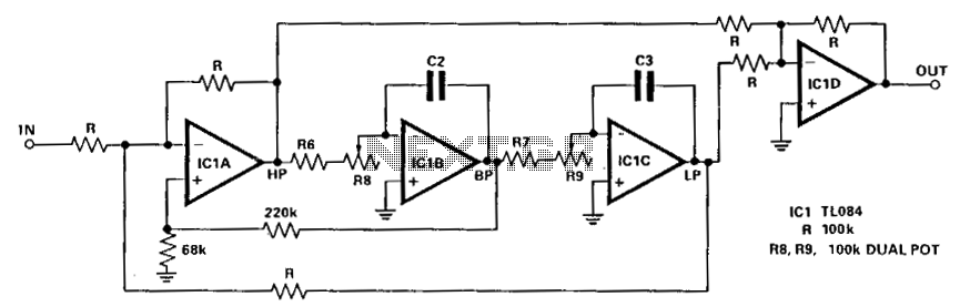
tl072 car subwoofer filter circuit

The subwoofer filter circuit is designed to enhance the bass response in audio systems, particularly in automotive environments where space and power constraints are prevalent. The TL072 opamp is chosen for its low noise and high-speed performance, which is essential for maintaining audio fidelity. The buffer configuration of IC1A ensures that the audio signal retains its integrity while allowing for impedance matching between the audio source and the filter circuit.
The DPDT switch S1 plays a critical role in the circuit by allowing the user to select between different configurations, enabling flexibility in the audio output. Positioning the switch to induce a 180-degree phase shift can help in optimizing the subwoofer performance, especially in setups where multiple speakers are used, ensuring that sound waves are properly aligned for a coherent audio experience.
Potentiometer R7 serves as a volume control, enabling the user to adjust the output level of the subwoofer, thus providing a tailored listening experience. The low-pass filter implemented by IC1B is crucial for eliminating high-frequency noise and allowing only the desired bass frequencies to pass through. The adjustable cutoff frequency, controlled by the dual gang potentiometer R13, provides the ability to fine-tune the filter's response, accommodating various audio preferences and speaker characteristics.
Overall, this subwoofer filter circuit is a versatile solution for enhancing low-frequency audio performance in automotive applications, combining simplicity and effectiveness in design.Here is the circuit diagram of an easy subwoofer filter that can be operated from a 12V DC supply. Such a circuit is incredibly helpful in automobile subwoofer applications. The circuit is nothing however a low pass filter whose pass frequency can be adjusted between 60 to 160 Hz. The circuit is designed based on the TL072 dual BIFET opamp IC. Out of the two opamps inside the chip, IC1A is wired as a buffer. The left and right audio inputs when mixing is fed to the input of the IC1A using the DPDT switch S1. Switch S1 is the part control switch which can be used to create the subwoofer in part with different speakers.
When S1 is in position 2, 180 degree part shift will be induced. POT R7 can be used for controlling the level. IC1B forms the low pass filter whose pass frequency can be controlled by adjusting the dual gang POT R13. 🔗 External reference
Related Circuits

The 555 timer integrated circuit (IC) is an exceptionally versatile component utilized in various applications, including generating clock pulses, switch debouncing, and functioning as an output transducer. The standard 555 IC is packaged in an 8-pin configuration, available in...
According to current legislation in many countries, vintage cars must be equipped with a rear fog lamp. Modern vehicles incorporate circuitry with the fog lamp switch to prevent the fog lamp from activating when the headlights are on, in...
The circuit illustrated here demonstrates that the response at one octave off-tune remains within 10% of the far-out response. The sharpness of the notch can be adjusted by increasing or decreasing the 68-ohm resistor. The linearity tracking of resistors...
This FM spy telephone circuit is connected in series with the phone line. When there is a signal on the wires, this transmitter will radiate airwaves through the wires. This FM spy telephone circuit operates by integrating with the existing...
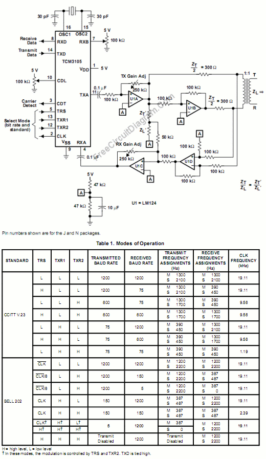
The TCM3105 FSK modem chip from Texas Instruments enables the construction of a modem compatible with Bell 202 or CCITT V23 standards. This modem circuit can transmit data at baud rates of 75, 150, 600, and 1200, and receive...
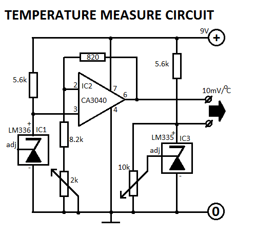
This circuit is designed for Fahrenheit measurements, with the freezing point set at 320°F. At 2120°F, P2 is adjusted to achieve an output voltage of 0.9V. The circuit operates by utilizing a temperature sensor that converts temperature readings into a...