
Rear Fog Lamp For Vintage Cars

The described circuit enhances the functionality of vintage vehicles by ensuring compliance with modern safety standards regarding fog lamp operation. The dual JK flip-flop architecture allows for reliable toggling of the fog lamp and indicator LED, providing visual feedback to the driver. The use of an emitter follower configuration with transistor T3 ensures that power is only supplied when needed, conserving energy and preventing unnecessary wear on components. The choice of tantalum capacitors for C1 and C2 is important for their stability and reliability in the circuit, especially under varying temperature conditions.
The debouncing circuit is critical for eliminating false triggering of the clock pulse, which could lead to erratic behavior of the fog lamp system. The inclusion of a free-wheeling diode (D2) is a common practice in relay circuits to protect sensitive components from voltage spikes caused by the inductive load of the relay coil. The Zener diode voltage-limiter circuit (D3 and R9) further enhances the robustness of the design by safeguarding against voltage fluctuations that could occur in older vehicle electrical systems.
Overall, this circuit design effectively retrofits modern fog lamp control technology into vintage vehicles, ensuring both functionality and compliance with current regulations while maintaining the integrity and reliability of the vehicle's electrical system.According to current legislation in many countries, vintage cars must also be fitted with a fog lamp at the rear. In modern cars, there is a bit of circuitry associated with the fog lamp switch to prevent the fog lamp from going on when the lights are switched on if the driver forgot to switch it off after the last patch of fog cleared up.
The cir cuit described here extends that technology back in time. The circuit is built around a dual JK flip-flop (type 4027). T3 acts as an emitter follower, and it only supplies power to the circuit when the lights are switched on. For safety reasons, the supply voltage is tapped off from the number plate lamp (L2), because it is on even if you accidentally drive with only the parking lights on.
The wire that leads to the number plate lamp usually originates at the fuse box. As the states of the outputs of IC1a and IC1b are arbitrary when power is switched on, the reset inputs are briefly set high by the combination of C1, R1 and T1 when the lights are switched on (ignition switch on). That causes both Q outputs (pins 1 and 15) to go low. IC1a and IC1b are wired in toggle mode (J and K high). The Set inputs are tied to ground (inactive). The driver uses pushbutton switch S1 to generate a clock pulse that causes the outputs of the flip-flops to toggle.
The debouncing circuit formed by C2, R4 and T2 is essential for obtaining a clean clock pulse, and thus for reliable operation of the circuit. C1 and C2 should preferably be tantalum capacitors. The Q output of IC1b directly drives LED D1 (a low-current type, and yellow according to the regulations).
The Q output of IC1a energises relay Re1 via T4 and thus applies power to the rear fog lamp L1. Free-wheeling diode D2 protects T4 against inductive voltage spikes that occur when the relay is de-energised. In older-model cars, the charging voltage of the generator or alternator is governed by a mechanical voltage regulator.
These regulators are less reliable than the electronic versions used in modern cars. For that reason, a Zener diode voltage-limiter circuit (D3 and R9) is included to keep the voltage at the emitter of T3 below 15 V and thus prevent the 4027 from being destroyed by an excessively high voltage. The supply voltage for the circuit is tapped off from the fuse box. An accessory terminal is usually present there. Check to make sure it is fed from the ignition switch. The pushbutton switch must be a momentary-contact type (not a latching type). Ensure that the pushbutton and LED have a good ground connection. Fit the LED close to the button. 🔗 External reference
Related Circuits

The circuit includes a CD4 component with a connection of 16 feet for the Vcc terminal, 8 feet for the ground, 12 feet for the reset terminal, 7 feet for the Qt end, and 3 feet for the Q...

This circuit is intended as a reliable replacement to thermally-activated switches used for Christmas tree lamp-flashing. The device formed by Q1, Q2 and related resistors triggers the SCR. Timing is provided by R1, R2 & C1. To change flashing...

The circuit operates on a 220V AC input, which is stepped down by a buck converter using resistor R3. The output voltage is rectified by a VDI rectifier and filtered through VD2 and capacitor C3, providing approximately 3.9V DC...

This article presents a driver circuit for a 12V, 5W fluorescent lamp. The circuit utilizes a standard 220V to 10V step-down transformer operated in reverse to achieve a 12V output. The driver circuit for a 12V, 5W fluorescent lamp is...
According to current legislation in many countries, vintage cars must also be fitted with a rear fog lamp. Modern vehicles incorporate circuitry associated with the fog lamp switch to prevent the fog lamp from activating when the lights are...
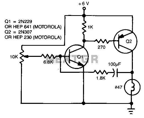
The flash rate is controlled by a complementary multivibrator consisting of an NPN and a PNP transistor. The complementary multivibrator circuit is a fundamental electronic configuration used to generate square wave signals, which can be employed for various applications including...