
TMP01 AD654 Temperature-to-Frequency Converter

The TMP01 is a temperature sensor that outputs a frequency signal proportional to the temperature it measures. This circuit is designed to convert the analog voltage output of the TMP01 into a frequency signal, which can be easily transmitted and processed in various applications, such as digital temperature monitoring systems.
In the TMP01 circuit, the temperature sensor operates by generating a voltage that corresponds to the ambient temperature. This voltage is then fed into a frequency converter, which typically consists of a voltage-to-frequency converter IC. The converter takes the analog voltage input and outputs a frequency signal, where the frequency is directly proportional to the input voltage.
The frequency output can be interfaced with microcontrollers or digital signal processors, allowing for straightforward digital processing and monitoring. This method of converting temperature to a frequency signal provides advantages such as improved noise immunity and the ability to transmit data over longer distances without significant signal degradation.
Typical components in this circuit may include the TMP01 temperature sensor, a voltage-to-frequency converter IC, resistors, capacitors, and possibly a microcontroller for further processing. The design considerations include ensuring the accuracy of the temperature measurement, the linearity of the frequency output, and the stability of the circuit under varying environmental conditions.
When implementing this circuit, attention must be paid to the power supply requirements of the TMP01 and the converter IC, as well as the layout of the circuit to minimize interference and ensure reliable operation.This is a TMP01 Temperature-to-Frequency Converter circuit. Converting voltage to the frequency domain is another common method of transmitting analog.. 🔗 External reference
Related Circuits
Anti-log or exponential generation involves rearranging logarithmic circuitry. The circuit diagram below illustrates the relevant circuitry. Anti-logarithmic or exponential circuits are essential in various applications, particularly in signal processing and analog computing. These circuits typically utilize operational amplifiers (op-amps) configured...
Normally, an analog-to-digital converter (ADC) requires interfacing through a chip to convert analog signals into digital format. This necessitates both hardware and software, resulting in increased complexity and overall cost. The circuit presented here is configured around the ADC...
The TPS6420x controller is designed to operate from one to three series-connected cells or from a 3.3 V or 5 V supply obtained from a USB port. At its output, it can produce 3.3 V at 2 A, suitable...
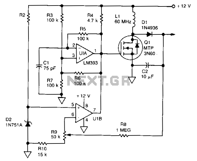
U1 is a dual voltage comparator with open collector outputs. The A side functions as an oscillator operating at 100 kHz, while the B side is part of the regulation circuit that compares a fraction of the output voltage...
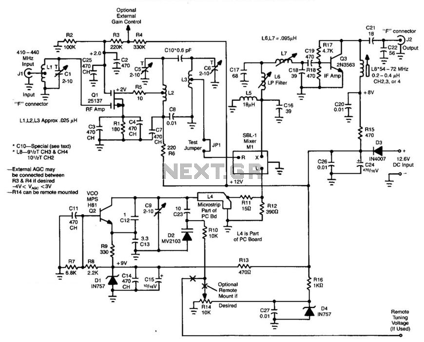
Ll, Ql, L2, and L3 form an RF amplifier stage that feeds Ml, a doubly balanced mixer. Q4 is a local oscillator stage operating in the 375-MHz range. Signals in the 420- to 450-MHz range from Ql are mixed...
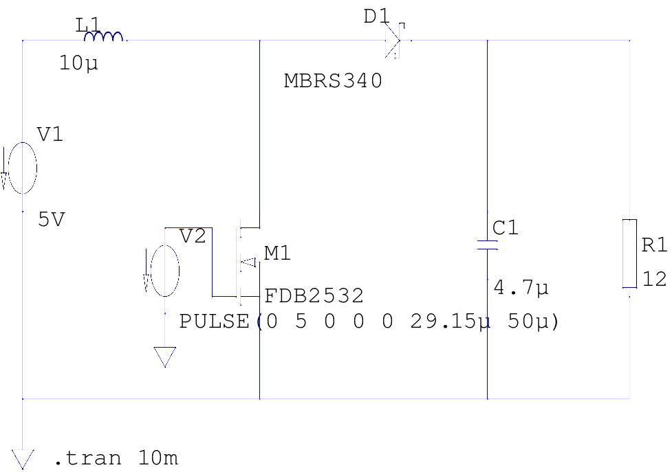
The supply voltage is 5V, and the goal is to increase it to 12V with a load current of 1A, resulting in an output power of 12W. A switching frequency of 20kHz has been selected, requiring a duty cycle...