
Low-Noise 420Mhz Atv Receiver/Converter

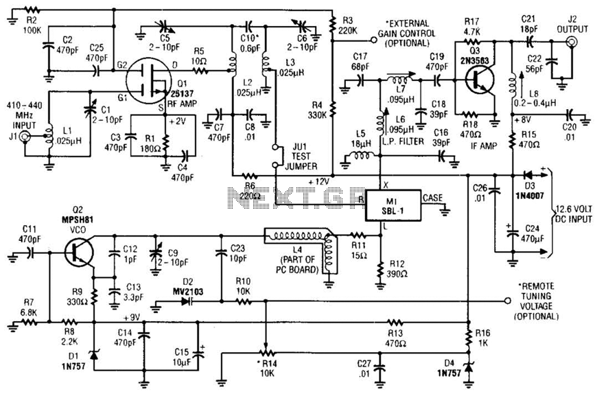
The circuit described consists of several critical components that work together to process radio frequency signals effectively. The RF amplifier stage, comprising inductors Ll, L2, L3, and transistor Ql, is designed to amplify the incoming RF signals before they are sent to the doubly balanced mixer, Ml. This mixer is crucial for converting the high-frequency RF signals into a lower intermediate frequency (IF) that can be more easily processed.
Q4 serves as the local oscillator, generating a stable frequency at 375 MHz. This frequency is mixed with the incoming RF signals, which range from 420 MHz to 450 MHz. The mixing process in Ml produces several frequency components, including the desired IF signals and unwanted spurious signals. To isolate the desired signals, a filter composed of inductors L6, L7, and capacitor C17 is employed. This filter is specifically designed to allow only the 60 MHz to 70 MHz signals, corresponding to channels CH3 and CH4, to pass through while attenuating other frequencies.
Once the desired IF signals are filtered, they are sent to Q3, which acts as the IF amplifier. This stage is critical for boosting the strength of the filtered signals to a usable level for further processing or demodulation. The overall gain of the circuit is specified at 25 dB, indicating a significant amplification of the signal. Additionally, the noise figure of less than 2 dB suggests that the circuit is designed to maintain a high signal-to-noise ratio, which is essential for achieving clear reception in RF applications. This combination of gain and low noise figure makes the circuit suitable for high-performance RF communication systems. Ll, Ql, L2, and L3 compose an RF amplifier stage that feeds Ml, a doubly balanced mixer. Q4 is a l ocal oscillator stage in the 375-MHz range. Signals in the 420- to 450-MHz range from Ql are mixed in Ml and fed through filter L6/L7/C17, where only the 60- to 70-MHz (CH3/CH4) signals pass. The IF signal is passed to Q3, an IF amplifier. The overall gain is 25 dB and the noise figure less than 2 dB.
Related Circuits
This RF converter converts amateur TV signals in the 420 to 450 MHz region to VHF channel 3 or 4, allowing reception of those signals on a standard TV receiver. RF amplifier Q1 feeds mixer M1, and Q3 acts...
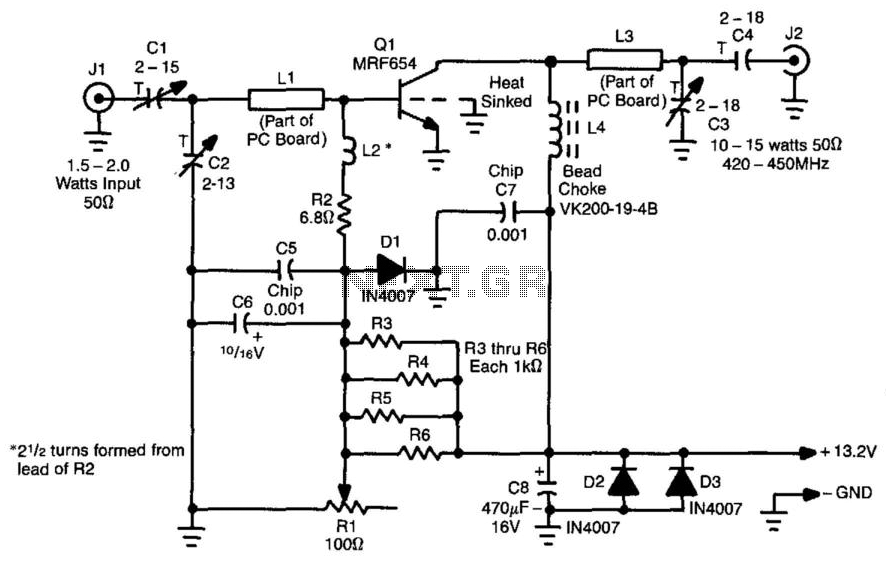
This amplifier is designed for applications requiring a peak-envelope-power (PEP) signal in the range of 10 to 15 watts, specifically within the 420 to 520 MHz frequency range. Components CI, C2, and LI create a matching network for amplifier...
The signal from a microphone is too weak for a standard line input. This low-noise DC-coupled microphone amplifier provides a solution for anyone who wants to connect a microphone to a high-fidelity installation. As illustrated in the schematic diagram,...
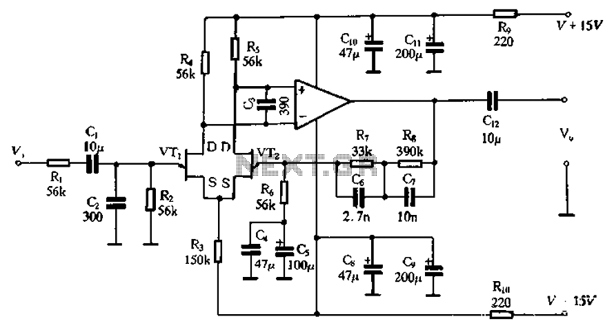
The circuit depicted in Figure 3-8 involves an input signal that passes through a low-pass filter before entering the differential amplifier. The composition of the FET (Field Effect Transistor) is evaluated at the preamplifier output. The differential amplifier connects...
836MHz RF2347 low noise amplifier circuit diagram. The RF2347 is a low noise amplifier (LNA) designed for operation at a frequency of 836 MHz. It is typically used in RF applications where signal amplification is critical, such as in communication...
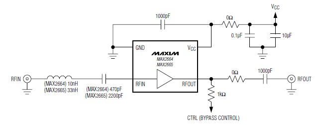
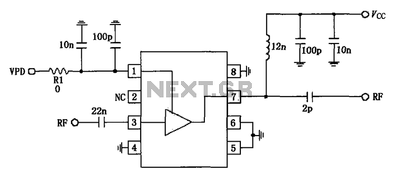
A simple, low-cost, and ultra-compact VHF/UHF low-noise amplifier circuit can be designed using the MAX2664 and MAX2665 ultra-compact LNAs for VHF/UHF applications. These devices incorporate a broadband LNA with an integrated bypass switch. The MAX2664 covers the UHF frequency...