
TMP01 Fahrenheit Scale Temperature Sensor

The TMP01 is a precision temperature sensor that provides an analog voltage output proportional to temperature. The circuit typically operates in the range of -40°C to +125°C, translating to a voltage output of 0V to 5V, where the output voltage increases with temperature. The sensor utilizes a bandgap reference to achieve high accuracy and stability over varying environmental conditions.
In this schematic, the TMP01 is connected to a power supply, usually +5V, which powers the sensor. The output voltage (VOUT) from the TMP01 is proportional to the temperature in Fahrenheit, calculated using the formula: VOUT = (Temperature in °F × 10mV) + 500mV. Hence, at 0°F, the output voltage will be 0.5V, and at 125°F, it will reach approximately 2.5V.
To interface the TMP01 with a microcontroller or other reading devices, the output can be connected to an analog-to-digital converter (ADC). This allows digital processing of the temperature reading. Additionally, a filtering capacitor may be added to the output to smooth the signal and reduce noise, ensuring a more stable reading.
The circuit may also include resistors for biasing and protection, as well as a calibration mechanism to ensure accurate temperature readings. Overall, this schematic provides a straightforward and effective means of measuring temperature in Fahrenheit using the TMP01 sensor.This schematic diagram is about TMP01 Fahrenheit Scale Temperature Sensor circuit. This circuit is used to convert VPTAT into an output that can be read.. 🔗 External reference
Related Circuits
IC1D is a CMOS Schmitt trigger oscillator at about 2KHz. It starts and continues to oscillate with a supply down to 1.24V (the lowest output voltage of my LM317 variable power supply) or less. IC1A is an inverter. IC1B...
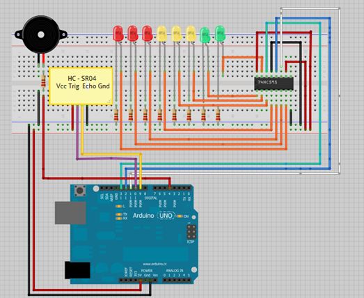
This is a tutorial for beginners who have recently started learning about electronics. The author has prior experience in programming with C and Python. The schematic presented in this tutorial is designed for novice electronics enthusiasts who are transitioning from...
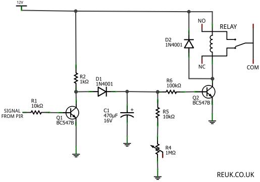
The focus is on 12 Volt DC powered PIR sensors and their associated circuits, which can be directly powered by a 12 Volt battery charged through renewable energy sources such as wind or solar. This article examines how the...
The Motion Sensor Switch circuit is an automatic water sprinkler controlled by a motion sensor, with the option to incorporate an alarm or light function. Before starting the construction, it is advisable to contact a local electronics component vendor...
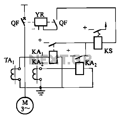
Figure 4-52 (a) illustrates the two-phase wiring for direct current (DC) operation, while Figure 4-52 (b) depicts the two-phase current differential wiring for alternating current (AC) operation. The schematic in Figure 4-52 (a) represents a two-phase wiring configuration suitable for...
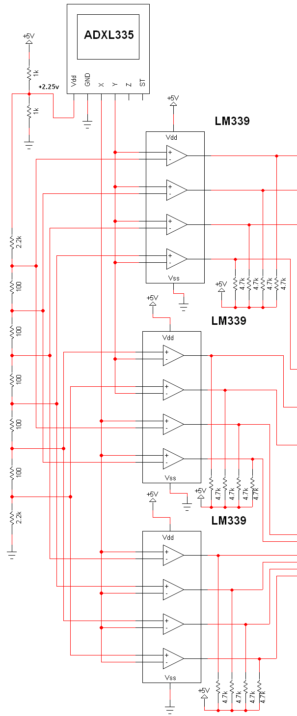
The schematic for this project is extensive, and the complete schematic is displayed below. It is divided into two sections: the analog and digital sections. The schematic illustrates the analog-to-digital conversion circuit, which includes 12 comparators—6 for the X-axis...