
Toggle Switch with relay

The described circuit utilizes a momentary push-to-make switch to control the operation of a relay. Upon the first press of the button, the relay coil is energized, allowing current to flow through the relay contacts, which can then control a connected load. A second press of the button interrupts the current to the relay coil, de-energizing it and opening the contacts, thus turning off the load.
The schematic includes a single-pole relay, but it is noted that a multi-pole relay can be used if the application requires multiple outputs to be controlled simultaneously. The relay's coil voltage is flexible, accommodating a range from 5 to 15 volts, which provides versatility in power supply selection. It is essential to choose a relay that matches the voltage of the power supply to ensure proper operation.
The push-to-make switch should be rated appropriately for the current and voltage levels expected in the circuit. When selecting the relay, parameters such as coil resistance, contact rating, and switching speed should also be considered based on the requirements of the load being controlled. The circuit can be implemented on a breadboard for prototyping or designed on a printed circuit board (PCB) for permanent installations.Pushing the button once will energize the relay. Pushing the same button a second time will de-energize the relay. Any simple momentary action push-to-make switch will do. I've drawn the circuit with a single pole relay. But you can use a multi-pole relay if it suits your application. The circuit will work at anything from 5 to 15-volts. All you need do is select a relay with a coil voltage that suits your supply. The LE 🔗 External reference
Related Circuits
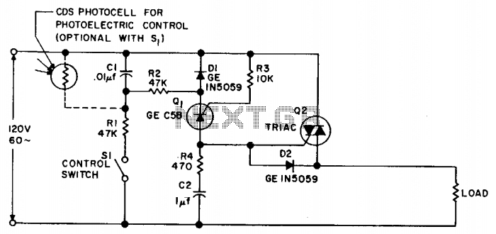
Synchronous switching activates only when the AC supply voltage crosses zero and deactivates only when the current reaches zero. This circuit responds to either a mechanical switch or a variable resistance, such as a cadmium-sulfide photocell. It minimizes disturbances...

The switch circuit consists of a capacitive oscillator, an integration network, and a comparator circuit that controls a relay. When a body comes close to the induction plate, the inductive capacitance to ground increases, causing the 555 astable multivibrator...
A circuit was assembled on a breadboard, which is divided into two sections. The right section is dedicated to generating a wailing alarm, while the left section is... The circuit design comprises two main functional blocks: the alarm generation circuit...
Using high-beam headlights while driving on the highway can significantly enhance visibility; however, they may pose a blinding risk to other drivers. This straightforward circuit can be integrated into the headlight switch to enable automatic switching between high and...
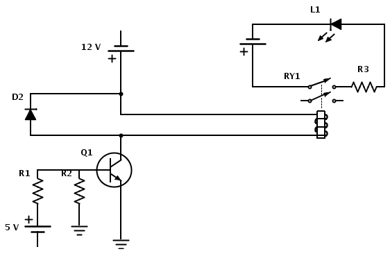
Create a circuit that enables the activation of a relay to control an LED. The relay operates at 12 V, while the available input voltage is 5 V. An NPN transistor will be utilized to switch the power to...
This circuit is constructed around a 555 timer and utilizes very few components. Due to its simplicity, even beginners can easily assemble and use it as a control device. A readily available laser pointer can be employed to operate...