
Tone-alert decoder

The described circuit utilizes a Phase-Locked Loop (PLL) mechanism to maintain synchronization with a reference signal, which is crucial for applications requiring precise frequency control, such as audio signal processing. The PLL circuit is configured with an external resistor (R2) that sets the frequency of operation. The LED indicator serves as a visual confirmation of the PLL's lock status, which is essential for troubleshooting and operational verification.
To fine-tune the PLL's frequency locking, the circuit incorporates a feedback loop where the signal level is adjusted using resistor R1. This adjustment process ensures that the PLL can lock onto the desired frequency reliably. The output from counter U3 provides a timing signal that introduces a delay, allowing for the stabilization of the PLL before activating the audio output.
The activation of transistor Q1 is a critical function of the circuit, as it controls the flow of audio signals to the speaker. The latch mechanism ensures that audio is only output when the PLL has achieved the correct frequency and duration, preventing unwanted noise or signal artifacts from reaching the speaker.
For reset functionality, the circuit design includes a provision to apply a temporary positive voltage to the R input of U4. This reset action is necessary for reinitializing the latch state, allowing the circuit to restart the frequency detection and locking process as needed. Overall, this configuration offers a robust solution for achieving reliable audio output based on precise frequency control.PLL (Ul) is set with R2 to desired tone frequency. LED lights to indicate lock-up of PLL. Reduce signal level (Rl) and readjust R2 to assure lock-up. Delay is selected from counter U3 output. Circuits latches (turns on Q1 to allow audio to speaker) when proper frequency/duration signal is received To reset latch, a positive voltage must be applied briefly to the R input of U4.
Related Circuits
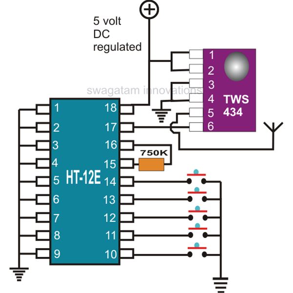
This document explains two RF 433kHz remote control chips specifically designed for remote control applications. The IC TWS-434, along with its encoder chip HT-12E from Holtek, forms a high-quality transmitter circuit, while the chip RWS-434, paired with the decoder...
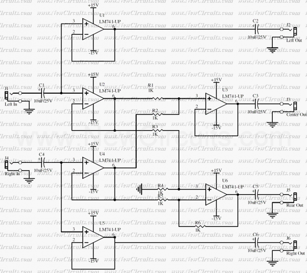
This is a simple surround sound decoder. Left & right outputs of a stereo tape or CD player can be connected to the circuit inputs and 4 outputs of the circuit can be connected to a surround power amplifier...
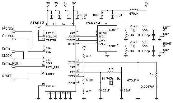
This page's mission is to assist in understanding the use of the STA013 MP3 decoder chip for designing an MP3 player. The player design outlined in subsequent pages utilizes the STA013, but this page aims to clarify the STA013...
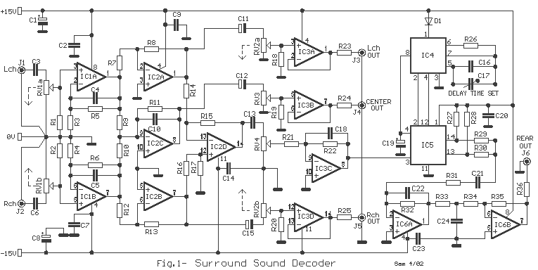
The particular circuit does not have the requirement to replace the trade decoders Surround, because they have many more facilities and possibilities. It gives, however, the possibility in many trials with this article of decoding. The coding in Stereo...
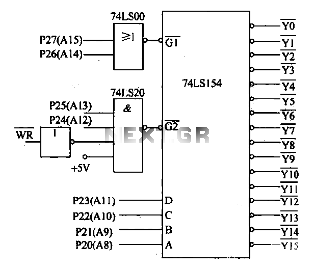
Decoding circuit: To ensure proper functionality of various interfaces, the system must assign IP addresses to all ports. Based on the number of system interfaces, it utilizes the 74LS154 decoder, which can translate up to 16 addresses. The interface...
This circuit can be utilized for Touch-Tone decoding as well as for telephone line and wireless control applications using a single audio frequency. The operating center frequency is determined by components H1 and C1. The resistor R1 should be...