
Address decoder interface circuit

The decoding circuit plays a critical role in managing the communication between multiple interfaces within a system. By employing the 74LS154, a 4-to-16 line decoder, the circuit can effectively assign unique IP addresses to each of the system's ports. This capability is crucial for ensuring that data packets are directed to the correct destinations, thereby maintaining the integrity of the communication process.
The address bus configuration, particularly the use of A15, A14, A13, and A12, enables the control of the decoder's operation. The G1 and G2 control terminals dictate whether the decoder is active, while the address lines A8 through A0 are responsible for selecting the specific output line corresponding to the desired port. This setup allows for efficient management of up to 16 different ports, facilitating a streamlined communication protocol.
Furthermore, the inclusion of eight D/A conversion circuits enhances the system's functionality by converting digital signals from the processor into analog voltages. The DAC0832 is a key component in this process, providing a reliable output range of 4-20 mA, which is standard for many industrial applications. This output can be used to control various actuators, such as motors or valves, allowing for precise manipulation of physical systems based on digital commands.
Overall, the combination of the decoding circuit and D/A conversion capabilities creates a robust framework for managing multiple interfaces and ensuring effective communication and control within the system. The design considerations and component choices reflect a thorough understanding of electronic principles and practical applications in the field.Decoding circuit: In order to make the various interfaces to work properly, the system needs to assign IP addresses to all ports. According to the number of system interfaces, it adopts the 74LS154, can be translated to 16 addresses, the interface circuit shown in Figure 27-50. The figure, the address bus A15, A14 control decoder control terminal Gl. A13, A12 control decoder control terminal G2. All-A8 connected decoder selection control terminal D, C, B, A. It can analyze each port address, see Table 27-2. In addition, the system also features eight D/A conversion circuit, respectively, to control the amount of output processor brightest converted into analog, sent to the corresponding actuators.
Use DAC0832, the output of 4-20mA.
Related Circuits
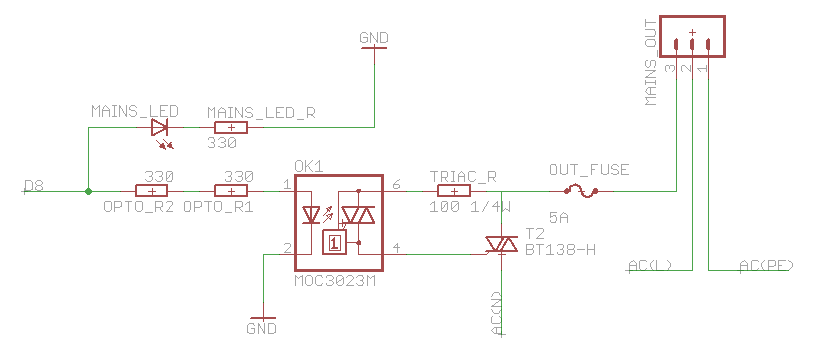
The heatsink on the triac is somewhat unclear. A maximum value of 10°C/W has been calculated, which raises concerns. The calculation is as follows: (maximum temperature - room temperature) / (maximum on-stage voltage * (milliamps / voltage) - junction-to-base...
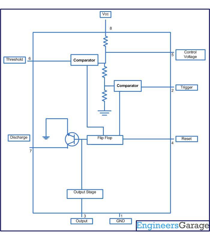
This circuit-based project demonstrates the operation of a 555 timer in astable mode to generate pulses with a time period of 0.5 seconds. These pulses can be utilized in various applications, such as blinking an LED or creating decorative...

This circuit is designed to be housed in a compact plastic or preferably metal enclosure, powered by a 9V battery. It features a level control, a male XLR connector (similar to those used in microphones), and a switch. The...
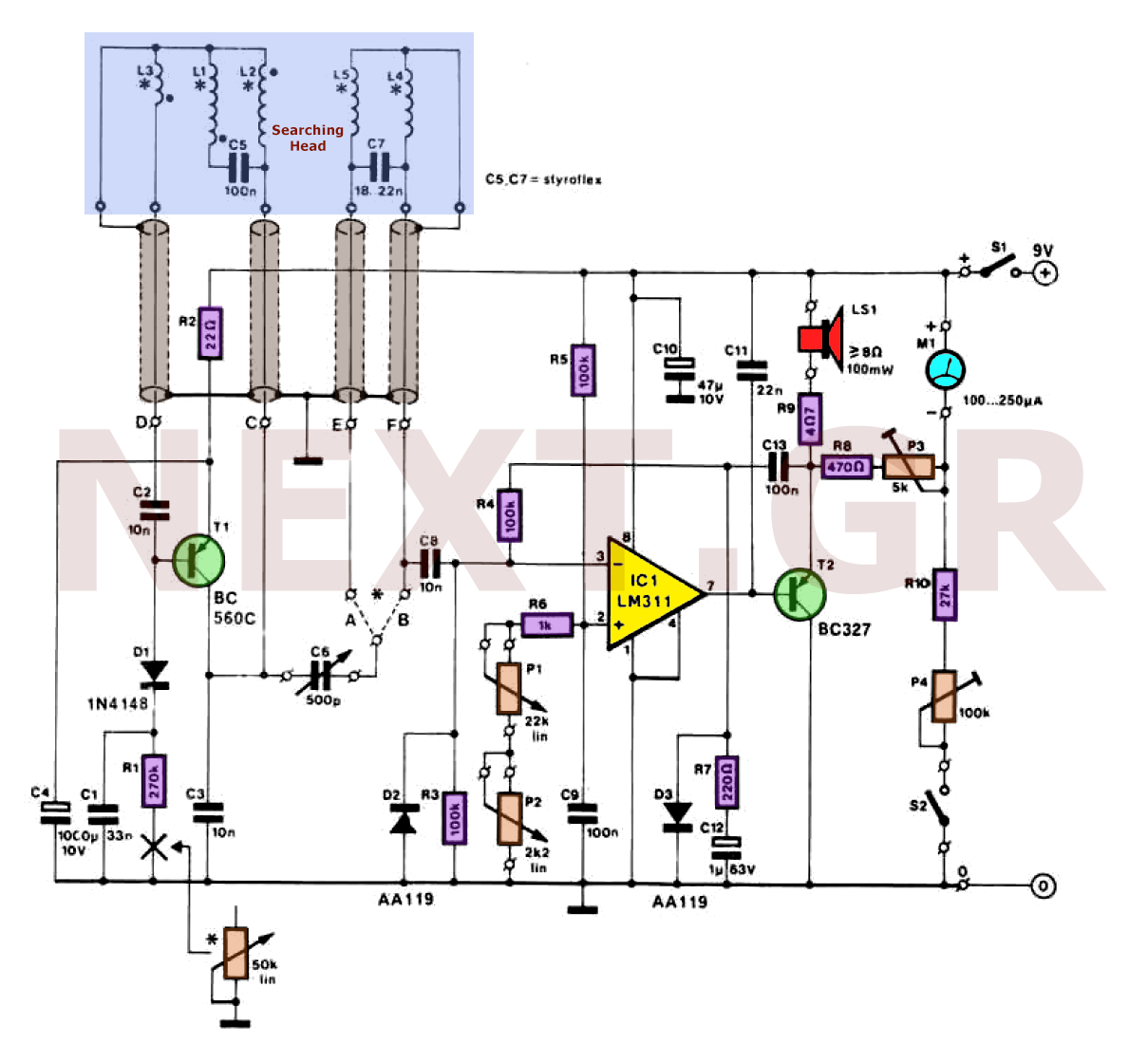
Metal detectors can be categorized based on their operational principles into three types: BFO (Beat Frequency Oscillator), TR/IB (Transmit-Induction/Balance), and PI (Pulsed Induction). Each method has its own set of advantages and disadvantages. An ideal metal detector, which does...
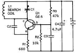
This metal detector circuit needs to be powered using a 9 volts power supply (DC) or a 9 volts battery. The C1 capacitor is a variable capacitor with a value of 365 pF, C2 is a 100 pF silver...
Gyrators are utilized in DC holding circuits, commonly found in Data Access Arrangements (DAAs). DAAs generally employ dry transformers that cannot handle DC current and include a DC blocking capacitor. When the telephone goes off-hook, it is necessary to...