
Tone burst generator

The circuit utilizes two timers, typically 555 timers, configured in distinct operational modes to generate audio tones. The first timer operates in monostable mode, which means it produces a single output pulse of a specific duration when triggered. This duration is defined by external resistors and capacitors connected to the timer. When a positive pulse is received at pin 6 (the trigger pin), the timer activates and the output remains high for a time period determined by the formula T = 1.1 * R * C, where T is the time in seconds, R is the resistance in ohms, and C is the capacitance in farads.
The output of the first timer serves as the trigger for the second timer. This second timer is configured in astable mode, allowing it to oscillate continuously between high and low states, thus generating a square wave output. The frequency of this oscillation, which ultimately determines the tone frequency, is also set by external resistors and capacitors. The frequency can be calculated using the formula f = 1.44 / ((R1 + 2*R2) * C), where R1 and R2 are the resistances in ohms, and C is the capacitance in farads.
In summary, the first timer's monostable configuration establishes the duration of the tone, while the second timer's astable configuration determines the frequency of that tone, allowing for a versatile tone generation circuit suitable for various applications such as alarms, sound effects, or musical notes. Proper selection of resistors and capacitors is crucial to achieving the desired audio characteristics.The first timer is used as amonostable and determines the tone duration when triggered by a positive pulse at pin 6. The second timer is enabled by the high output of the monostable It is connected as an astable and determines the frequency of the tone.
Related Circuits
A rectangular-wave pulse generator with an extremely long period can be constructed using only two components: a National Semiconductor LM3710 supervisor integrated circuit (IC) and a 100-nF capacitor to suppress noise spikes. This circuit leverages the watchdog and reset...
The LM1036 is a DC controlled tone (bass/treble), volume and balance circuit for stereo applications in car radio, TV and audio systems. An additional control input allows loudness compensation to be simply effected. Four control inputs provide control of...
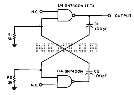
With the values shown, the circuit generates a 2-MHz symmetrical square wave. Changing capacitors C1 and C2 to 0.01 µF results in a frequency of 500 Hz. For the particular integrated circuits and power supply voltages (5.0 V), the...
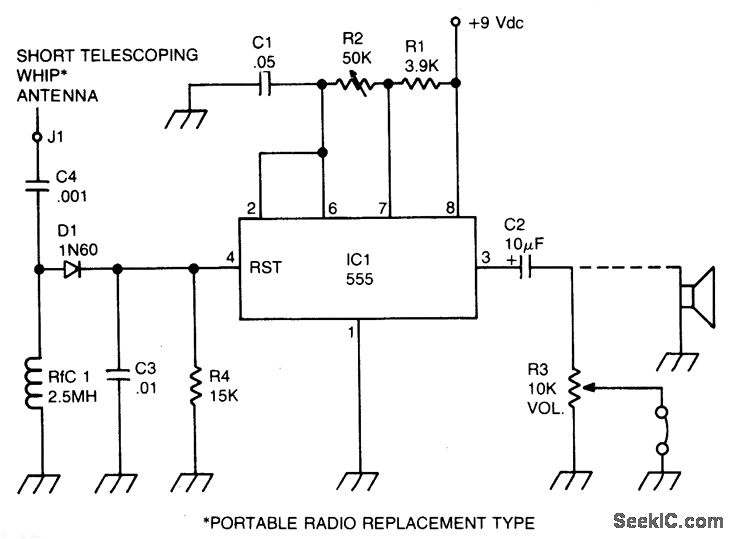
A sidetone oscillator is a specialized audio oscillator that is activated and deactivated in conjunction with the transmitter. This oscillator is driven by RF signals and is powered by batteries. It employs a 555 integrated circuit (IC) timer configured...
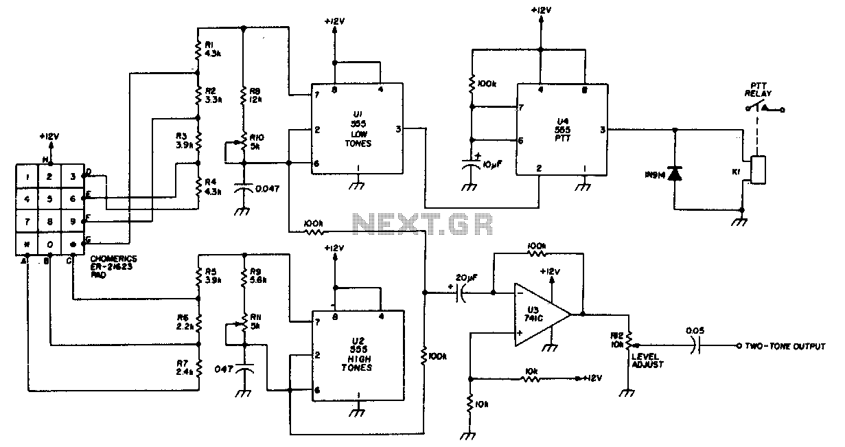
Tone dial encoder with automatic PIT control. It utilizes 555 timers. The tone dial encoder with automatic Pulse Interval Timer (PIT) control is an electronic circuit designed to generate specific tone frequencies for dialing systems, commonly found in telecommunication devices....

This circuit design generates a stable 1 kHz sine wave using an inverted Wien bridge configuration with components C1-R3 and C2-R4. It offers a variable output, low distortion, and low output impedance to ensure good overload capability. The circuit...