
RE POWERED SIDETONE OSCILLATOR

The sidetone oscillator plays a crucial role in communication systems, particularly in radio transmission. It provides an audio feedback signal that allows the operator to monitor the transmitted signal. The 555 timer, functioning as an astable multivibrator, produces a continuous square wave output, which can be adjusted in frequency by varying the external resistors and capacitors connected to it.
In this configuration, the RF-driven aspect of the oscillator ensures that it operates in sync with the transmitter's signal. When the transmitter is keyed, the RF signal generates a positive DC potential that resets the 555 timer, effectively turning the oscillator on. This results in an audible tone that corresponds to the transmission, allowing the operator to hear the sidetone while transmitting.
The circuit typically includes a few passive components such as resistors and capacitors, which determine the frequency and duty cycle of the output waveform. Additionally, a speaker or audio output device is connected to the output of the 555 timer to convert the electrical signal into sound. The battery operation makes the sidetone oscillator portable and suitable for various applications in field communication setups.
Overall, the sidetone oscillator enhances the usability of radio transmitters by providing essential audio feedback, contributing to effective communication practices.A sidetone oscillator is a special audio oscillator that is turned on and off with the transmitter. The oscillator is rf-driven and bat-tery operated. It uses a 555 IC timer as an astable multivibrator. Keying is accomplished by applying a positive dc potential, developed from the rf signal, to the reset terminal of the 555. 🔗 External reference
Related Circuits
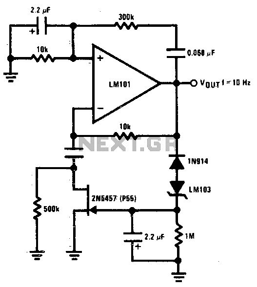
The 2N5457 JFET is utilized as a voltage variable resistor within the amplifier feedback loop, resulting in a low distortion, constant amplitude sine wave and optimizing the amplifier loop gain. The LM103 zener diode serves as the voltage reference...
A battery-powered, pushbutton-triggered TTL/CMOS-compatible source of debounced 5V logic pulses is a simple but handy piece of test equipment to have in any tool kit. The circuit's battery-powered operation complicates what would otherwise be a trivial exercise in switch-bounce...
This receiver is MC3371. Pin 16 is the RF input to the mixer and pin 1 and pin 2 is the local oscillator. The product comes out at pin 3. Imagine you want to receive at 100MHz. The local...
The output frequency can be altered based on the division ratio of the comparison frequency in the 10 kHz unit, with the division ratio set to 1024 in this circuit. Given that the amateur radio bandwidth in Japan is...
This oscillator generates low-distortion sine waves within a frequency range of 16 to 22,000 Hz. The sine wave oscillator is designed to produce high-quality sine wave outputs with minimal distortion across a wide frequency spectrum. The operational range of 16...
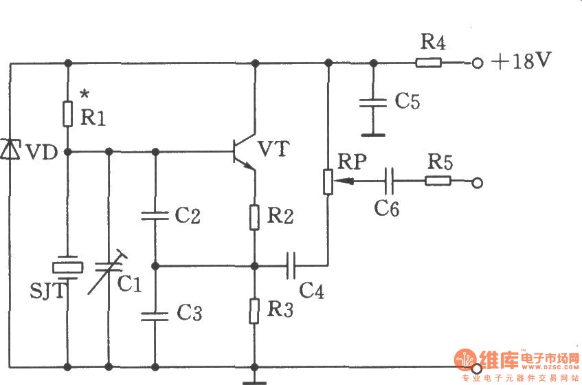
The figure illustrates the Colpitts oscillator circuit, which utilizes a base frequency crystal. The operating frequency is 1499 kHz, with the crystal SJT connected to both ends of capacitors C2 and C3. The emitter divider resistors R2 and R3...