
Tone Control

This circuit design utilizes operational amplifiers (op-amps) to achieve independent control over the bass and treble frequencies, allowing for enhanced audio customization. The preamplifier stage amplifies the audio signal before it is processed by the tone control section.
The bass control typically employs a low-pass filter configuration, which allows lower frequencies to pass through while attenuating higher frequencies. This is achieved by using capacitors and resistors in a feedback loop with the op-amp, where the cutoff frequency can be adjusted to the desired level.
Conversely, the treble control is implemented using a high-pass filter arrangement, permitting higher frequencies to pass while reducing the amplitude of lower frequencies. Similar to the bass control, this section also utilizes capacitors and resistors, with the op-amp configured to allow for fine-tuning of the treble response.
The output from both tone control sections can be mixed and fed into the output stage of the preamplifier, which may include additional amplification or buffering to drive the next stage in the audio signal chain. Power supply decoupling capacitors are also recommended to ensure stable operation and to minimize noise in the audio signal.
Overall, this preamplifier circuit with independent Bass and Treble controls is ideal for applications requiring customizable audio output, such as in home audio systems, musical instruments, or professional audio equipment. Proper layout and component selection are crucial for achieving optimal performance and minimizing distortion in the final output.Bass Treble Tone Control Circuit A preamplifier circuit providing independent Bass and Treble tone controls is shown in this circuit. The.. 🔗 External reference
Related Circuits
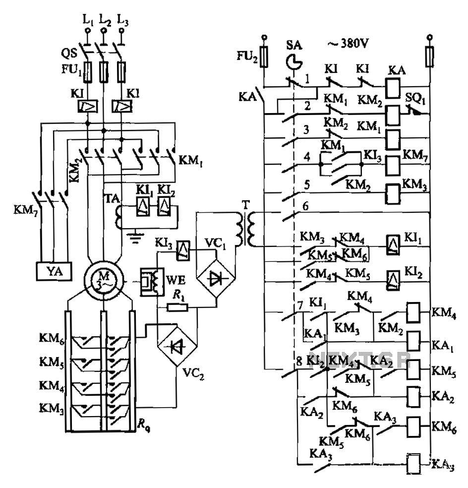
Attached to the wall is a high-rise building construction elevator, an essential piece of vertical transportation machinery. Its drive motor is typically a wound wire induction motor. The main switch and eddy current brake controls are also mounted on...
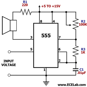
The objective is to identify a function generator or a voltage-controlled oscillator (VCO) suitable for generating two sine wave sound signals. One waveform should be fixed at a frequency, such as 440 Hz, while the second waveform must be...
Described here is a very inexpensive solution to many phono-controlled applications like remote switching on, for instance, or activating a camera, tape recorder, burglar alarms, toys, etc. The circuit given here employs a condenser microphone as the pick-up. A...
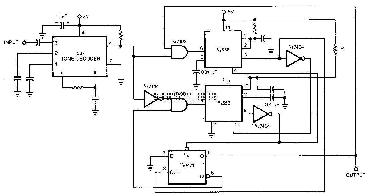
Adding a pair of monostable multivibrators to the output of a 567 tone decoder reduces its sensitivity to out-of-band signals and noise. In the absence of these multivibrators, the 567 is susceptible to unwanted output chatter. Alternative protection methods,...
This tutorial explains how to read the content of a microcontroller's flash memory. The source microcontroller reads the memory content and displays it on the LEDs. The content consists of the program stored in the microcontroller's memory. This step...
This is a TV remote control jammer circuit. Remote controls use modulated light to combat interference from background infrared noise. Your room heater, etc. The TV remote control jammer circuit is designed to disrupt the operation of infrared remote controls...