
tv remote control jammer

The TV remote control jammer circuit is designed to disrupt the operation of infrared remote controls by emitting modulated infrared signals that interfere with the signals sent from the remote control to the television. This circuit typically consists of an infrared LED, a modulation circuit, and a power supply.
The infrared LED serves as the primary emitter of the jamming signal. It is driven by a modulation circuit that generates a pulsed signal at a frequency similar to that of standard remote control devices, which typically operate in the range of 30 kHz to 40 kHz. This modulation is crucial as it allows the jammer to effectively mask the signals emitted by legitimate remote controls.
The power supply for the circuit can be a simple battery or a regulated power source, depending on the design requirements. It is essential to ensure that the power supply provides sufficient current to the infrared LED for effective jamming without overheating or damaging the components.
In terms of layout, the circuit should be designed to minimize interference with other electronic devices and should incorporate proper shielding to prevent unintended emissions. The use of a microcontroller can enhance the functionality of the jammer by allowing for adjustable modulation frequencies and the ability to turn the jamming signal on and off as needed.
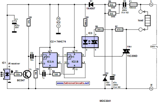
Safety and legal considerations must be taken into account when using or building a remote control jammer, as jamming signals can interfere with legitimate communications and may be regulated or prohibited in certain jurisdictions.This is a TV Remote Control Jammer circuit. Remote control use modulated light to combat eer infrared nvironment/background infrared noise. Your room heater,.. 🔗 External reference
Related Circuits
This digital volume control has no pot to wear out and introduces almost no noise in the circuit. Instead, the volume is controlled by pressing UP and DOWN buttons. This simple circuit would be a great touch to any...
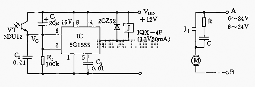
The control circuit consists of an NE555 timer and a phototransistor, along with resistors R1, capacitors C1 and C2, among other components. The photodiodes 3DU12 respond to sunlight by decreasing their resistance, which causes the voltage at the 555...
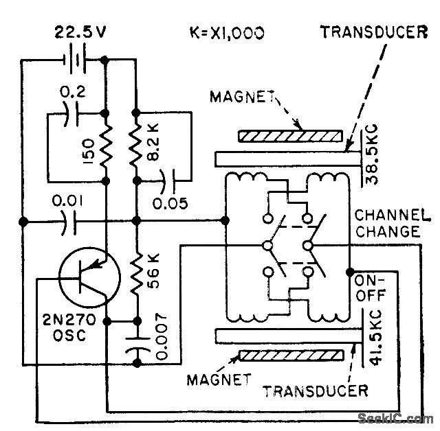
The frequency of a transistor oscillator is regulated by two different lengths of nickel tubing, each containing two coil windings. One coil functions as a driver, while the other serves as a pickup to generate feedback voltage necessary for...
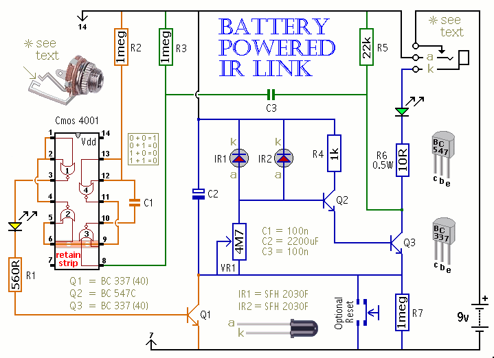
This is a battery-powered infrared (IR) link that can be utilized in multiple rooms. The standby current is exceptionally low, resulting in excellent battery life. The circuit is designed to shut down when faced with extraneous IR radiation, effectively...
Most homes today have at least a few infrared remote controls, whether for the television, video recorder, stereo, etc. However, many people have experienced frustration when the light remains lit after settling down in a comfortable chair to watch...
The control voltage is fed into the first half of a 1458 op-amp, this stage inverts the signal and sets the offset and gain for the right channel gain control circuit. This signal is then fed into the second...