
Tone Control Using TDA1524

The TDA 1524 is a versatile tone control IC widely used in audio applications for its ability to integrate multiple functions into a single package. It incorporates a preamplifier, bass, treble, and balance controls, providing a comprehensive solution for audio signal processing. The IC operates with an external power supply, typically ranging from 12V to 18V, and is designed to handle input signals from various audio sources.
In the schematic, the audio input is fed into the TDA 1524, where it is processed through the internal circuitry. The potentiometer connected in series allows for real-time adjustments to the audio signal. By varying the resistance, the voltage at the center terminal of the potentiometer changes, which in turn alters the gain and frequency response of the audio output. This feature enables users to tailor the sound to their preferences, enhancing the listening experience.
The output from the TDA 1524 can be connected to a power amplifier or directly to speakers, depending on the design requirements. It is essential to implement proper filtering and decoupling capacitors in the circuit to minimize noise and ensure stable operation. Additionally, it is advisable to include a bypass capacitor close to the power supply pins of the IC to further enhance performance.
Overall, this circuit diagram serves as an effective tool for audio tone control, providing flexibility and ease of use through the integration of the TDA 1524 IC and the potentiometer configuration.Circuit diagram is one of the circuit diagram to set the tone. Circuit diagram This is controlled by using the tone control IC TDA 1524 the type that includes all of the balance of bass and treble volume in one IC TDA 1524 a. You can setting a potentiometer, in several series, changes the voltage on the center potensio ic work
🔗 External reference
Related Circuits
A circuit has been constructed based on a design from Silicon Chip magazine to test bipolar stepper motor collections. The circuit is easy to build and functions effectively. The described circuit is designed to facilitate the testing of bipolar stepper...
This circuit could be used for replacing your manual volume control in a stereo amplifier. In this circuit, push-to-on switch S1 controls the forward (volume increase) operation of both channels while a similar switch S2 controls reverse (volume decrease)...
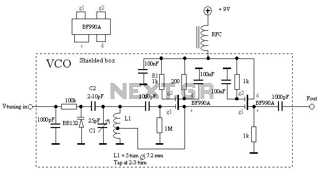
The VCO is based on a Hartley oscillator. The frequency is determined by L1 and capacitor C1. The tuning voltage will change the capacitance in the varactor BB132 which will change the oscillation frequency. The value of capacitor C2...
When the water level is low, the wires in the tank are open-circuited, and the 180K resistor pulls the switch low, resulting in the switch opening and the LEDs turning OFF. As the water begins to fill the tank,...
.jpg)
This is a general-purpose remote control project utilizing programmable PIC microcontrollers (PIC16F628, PIC16F630, PIC16F684). Schematics are provided for using infrared (IR) or radio frequency (RF) media. For those unfamiliar with microcontroller programming, fixed encoder and decoder integrated circuits can...
A USB solution is required for a project utilizing the LPC2148 microcontroller (MCU). In the past, interfaces such as LPT or COM were commonly used to connect projects to a PC, but these have become obsolete. The project allows...