
Microcontroller USB HID 4-bytes in 4-bytes out

The USB solution for the LPC2148 MCU project is structured to facilitate both data communication and power supply through a single USB connection. This dual functionality is particularly beneficial in modern applications, reducing the complexity of wiring and enhancing portability. The LPC2148 microcontroller, known for its efficiency and performance, is capable of handling multiple I/O operations, making it suitable for interfacing with various peripherals.
In this design, the USB communication is implemented using a polling mechanism, which allows the MCU to remain in a low-power state until a request is received from the host PC. This method conserves energy and extends the operational life of battery-powered applications. The use of a Visual Basic program on the PC side simplifies user interaction, enabling easy control and monitoring of the connected peripherals.
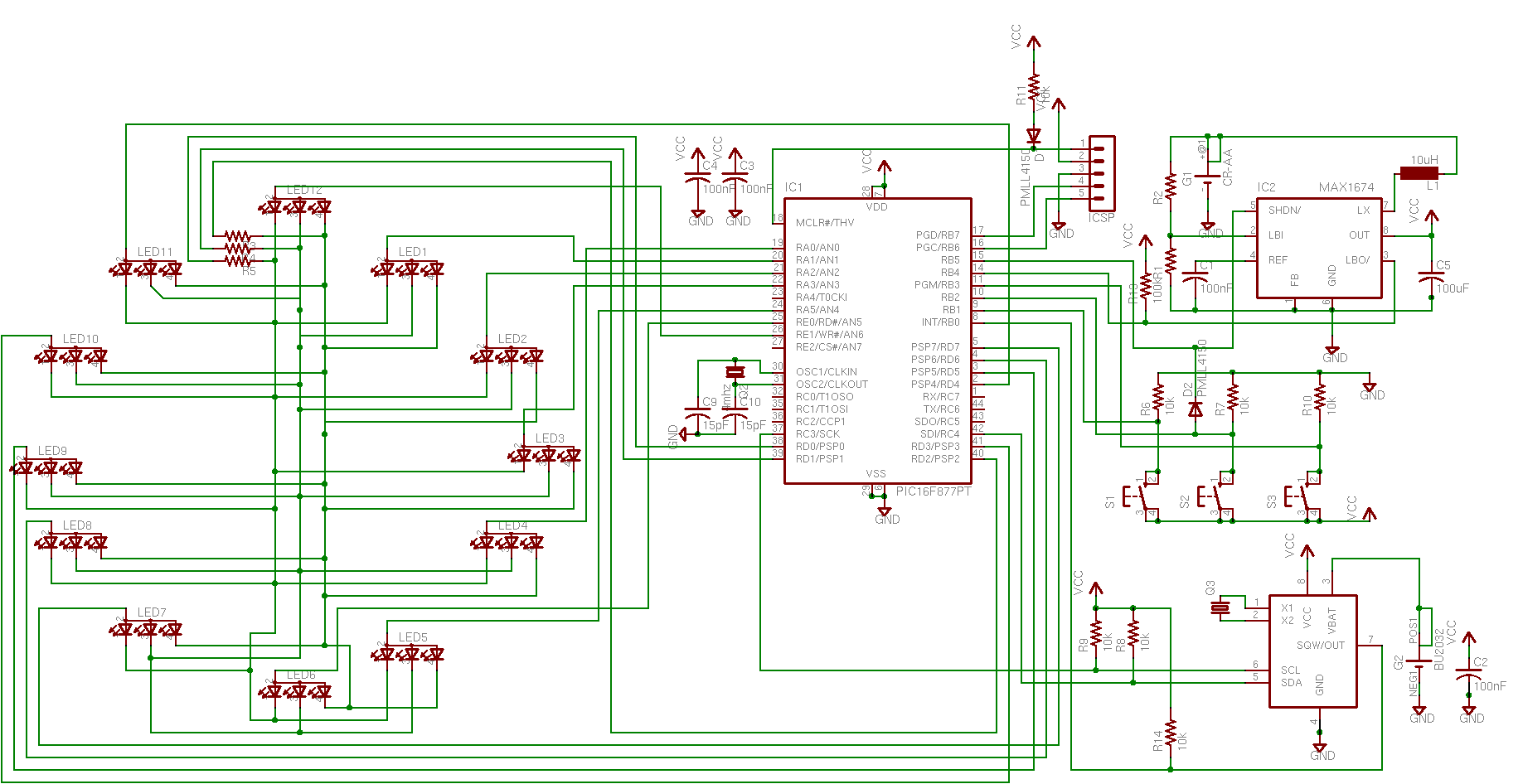
The circuit employs 10k pull-up resistors for the switches, ensuring reliable high signal levels when the switches are open. The inclusion of 120-ohm resistors in series with the LEDs protects the GPIO pins from excess current, which is critical for maintaining the integrity of the MCU over time. The choice of the LM1117-3.3 voltage regulator is appropriate for stepping down the USB 5V supply to the required 3.3V for the MCU, ensuring stable operation.
It is essential to consider the current limitations of USB ports, especially in portable devices. The design should accommodate the possibility of higher current draws, particularly if additional peripherals are connected or if the application requires significant power. Implementing an external power supply option can mitigate these limitations, ensuring consistent operation across different devices. In summary, this USB solution for the LPC2148 MCU is a robust and flexible approach to modern electronic project design, catering to both power and data communication needs.Need USB solution for your project Use LPC2148 MCU. In old days it`s very handy using LPT or COM to interface your project to PC but today they are vanished just like dinosaur. All switch status can be monitored on the PC, as well as the ADC value. The LEDs are turn on/off by the first byte sent from PC. In my project input and output buffer size are 4 bytes each, you can increase the buffer depends on your need. To me, this project is about perfect because the program on PC can recover the connectionwhen temporary USB cable disconnection occurs. The VB program recognize the device from its Vendor ID (C251) and Product ID (1301). Thiscircuit work onpoll-based communication, meaning theMCU will reply when receive request fromPC. So when USB disconnected, there is no update on LCD. There are 8 switches pulled-up by 10k resistors and8 LEDs with 120ohmseries current reducer so that the GPIO will not burn out by the overload sink current.
Power comes from USB +5V, regulated down to 3. 3V by LM1117-3. 3. It`s very handy, isn`t it USB connection provides both data link and power supply. Just put in your consideration that the +5V is limited to 500-1000mA, depends on the PC/notebook/netbook type. Some older notebook even limit the current up to 100mA only. If your project require big current, it`s wise to prepare an external power supply. Just like the USB external harddisk configuration, when the PC power is insufficient the harddisk should be connected to 2 USB ports or using external 5V power.
🔗 External reference
Related Circuits
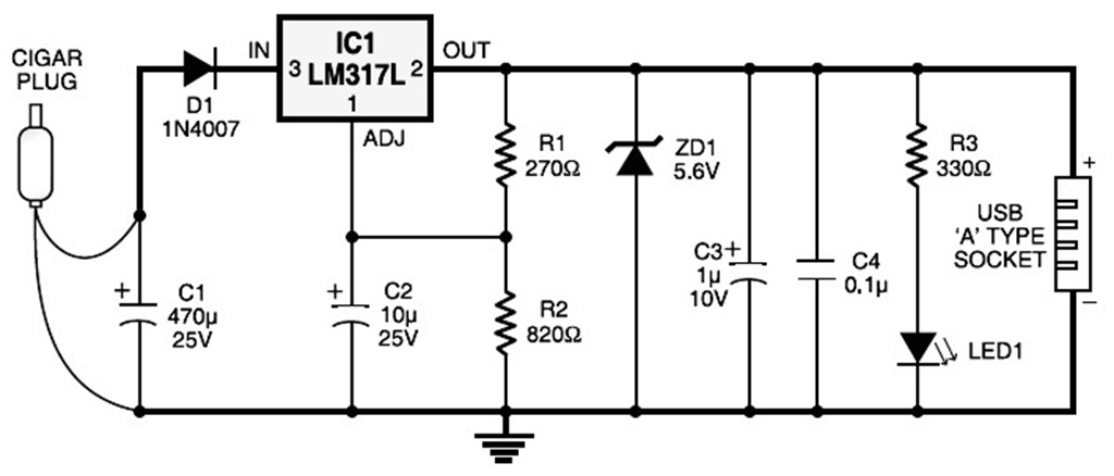
The diagram illustrates the circuit of a versatile USB power socket that safely converts 12V battery voltage into a stable 5V output. This circuit enables the use of various USB-powered devices. The circuit design consists of several key components to...
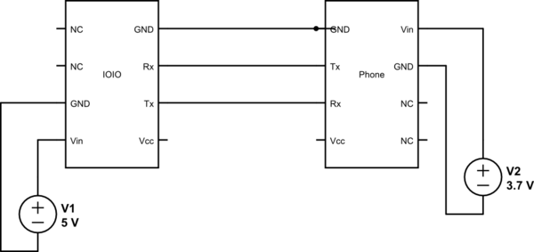
This project utilizes Sparkfun's IOIO for Android, focusing on power consumption concerns. The IOIO board can provide the phone with 500 mA charging, which may be excessive for continuous operation. The proposed solution is to power both the phone...
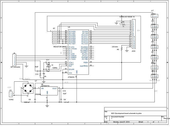
DTMF-based Robo Car design using the 8051 microcontroller project. This project demonstrates a method to control a domestic system using the DTMF tone generated by a telephone instrument when the user presses the keypad buttons of a mobile phone...
A USB port is capable of supplying more than 100 mA of continuous electric current at 5V to peripherals connected to the bus. This feature allows a USB port to power 5V DC-operated small electronic devices without issues. Many...
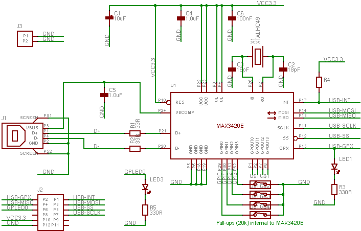
The MAX3420 is a USB peripheral controller chip featuring an SPI bus. This document aims to provide sufficient information for effective utilization of the device in various projects. The MAX3420 simplifies the integration of a USB interface into a...
With the phasing out of game, serial, and parallel ports from modern computers and the increasing popularity of USB, it is beneficial for hobbyists to learn how to work with USB. However, USB is a complex protocol that can...