
tone decoder

The dual time constant tone decoder circuit is designed to optimize the performance characteristics required for specific applications, particularly in communication systems where signal fidelity and quick response to tone changes are paramount. The operational principle relies on the dynamic switching of capacitors to manipulate the filter characteristics based on the presence of input signals.
Capacitor C2 serves as the primary filter element when no tone is detected, ensuring a rapid response time due to its minimized capacitance, which allows for quick charge and discharge cycles. This characteristic is essential in applications where swift detection of tone signals is necessary to maintain system responsiveness.
Upon the detection of a tone signal, transistor Qj is activated, resulting in the integration of capacitor C'2 into the circuit. This capacitor, which can be significantly larger than C2, effectively reduces the overall cutoff frequency of the low-pass filter, thus narrowing the bandwidth. The ability to adjust the bandwidth dynamically is particularly advantageous in environments with varying signal conditions, enabling the circuit to filter out unwanted noise while maintaining the integrity of the desired tone signal.
The design of the dual time constant tone decoder circuit exemplifies a sophisticated approach to signal processing, where the interplay between capacitors allows for tailored filtering characteristics that can adapt to the demands of different applications. This adaptability is crucial in ensuring effective communication in various electronic systems, from simple tone detection to complex communication protocols.For some applications it is important to have a tone decoder with narrow bandwidth and fast response time. This can be accomplished by the dual time constant tone decoder circuit shown. The circuit has two low-pass loop filter capacitors, C2 and C'2. With no input signal present, the output at pin 8 is high, transistor Qj is off, and C'2 is switched out of the circuit.
Thus, the loop low-pass filter is comprised of C2, which can be kept as small as possible for minimum response time. When an in-band signal is detected, the output at pin 8 will go low, will turn on, and capacitor C'2 will be switched in parallel with capacitor C2.
The low-pass filter capacitance will then be C2 + C'2. The value of C'2 can be quite large in order to achieve narrow bandwidth. During the time that no input signal is being received, the bandwidth is determined by capacitor C2.
Related Circuits
This project displays telephone numbers decoded from tones. A microphone picks up the tones, a preamplifier boosts the signals, an SSI-202 DTMF chip decodes the tones, a Basic Stamp acts as an interface to an LCD display and also...
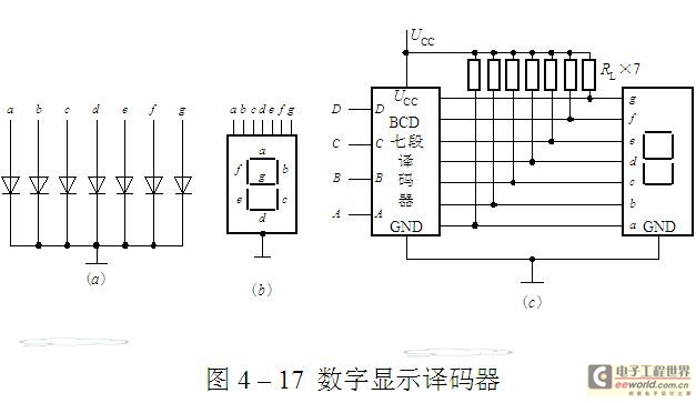
The luminescent diode (LED) is constructed from gallium arsenide (GaAs), a specialized semiconductor material, and gallium arsenide phosphide. It can be used individually or assembled into segment-type or lattice LED display devices. The display unit consists of a sectional...
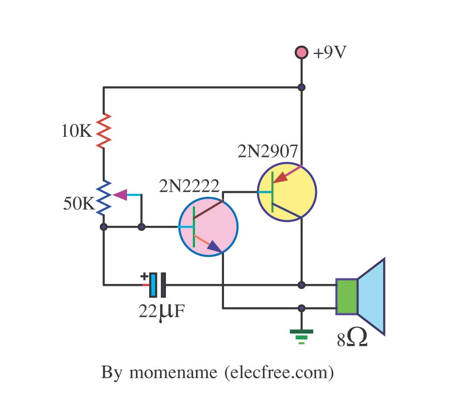
This is a simple tone oscillator generator. It uses the transistors 2N2222 and 2N2907 as the main components. The tone sound is controlled with a 50K ohm resistor (R2) and an 8-ohm speaker is utilized. The tone oscillator generator circuit...
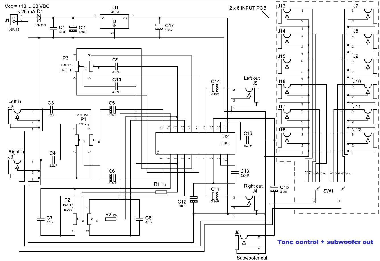
PT2350 is a tone control subwoofer crossover low pass filter chip utilizing CMOS technology. It features a tone control range of +10dB (50Hz, 4 kHz) and a subwoofer low pass filter of the second-order Sallen Key design. The roll-off...
This is an image Schematic. No Description available. The provided input indicates that there is a schematic image, but no additional descriptive information is available regarding its components, functionality, or application. In the context of electronic schematics, such images...
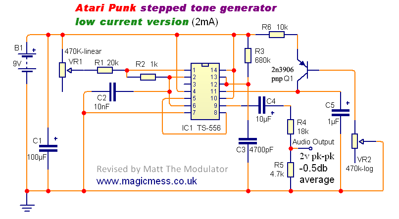
The Stepped Tone Generator is a dual oscillator circuit that produces a single pulse wave output. The first oscillator controls the pitch of the output oscillator, which divides the pitch into progressively smaller amounts based on its pulse width...