
The 6090 Digital Decoder

No description available.
Related Circuits
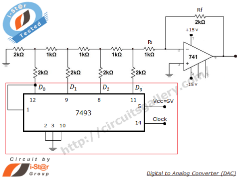
A Digital to Analog Converter (DAC) is utilized to produce an analog voltage that corresponds to input digital data. Binary data can be transformed into its analog equivalent using an R-2R ladder network combined with a summing amplifier, which...
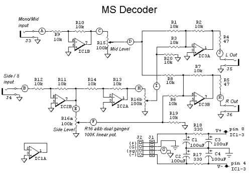
The schematic diagram of the MS Decoder may appear complex, but it is relatively straightforward. Initially, both the Mid and Side signals are buffered using unity gain inverting buffers, which are constructed around IC1b and IC2b. This buffering serves...
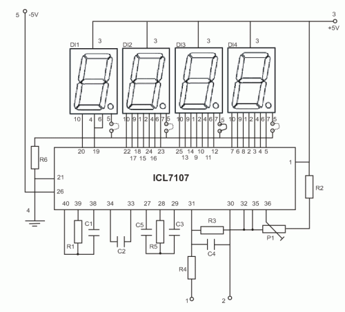
The copyright of this circuit is owned by Smart Kit Electronics. This document discusses improvements and modifications based on the original schematic. It describes a straightforward yet highly accurate and useful digital voltmeter designed as a panel meter, suitable...
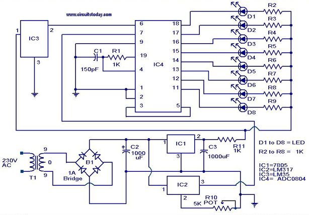
A digital temperature sensor circuit is explained with a circuit diagram. ICs ADC 0804, LM35, and LM317 are used in this digital circuit project. The digital temperature sensor circuit utilizes three primary integrated circuits (ICs): the ADC 0804, LM35, and...
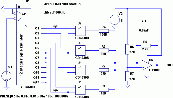
The schematic diagram depicted in Figure 1 is designed to synthesize a sinusoidal waveform with a frequency range of 0.01 Hz to 1 MHz. A clock signal is supplied to the input of the binary counter IC1, with a...
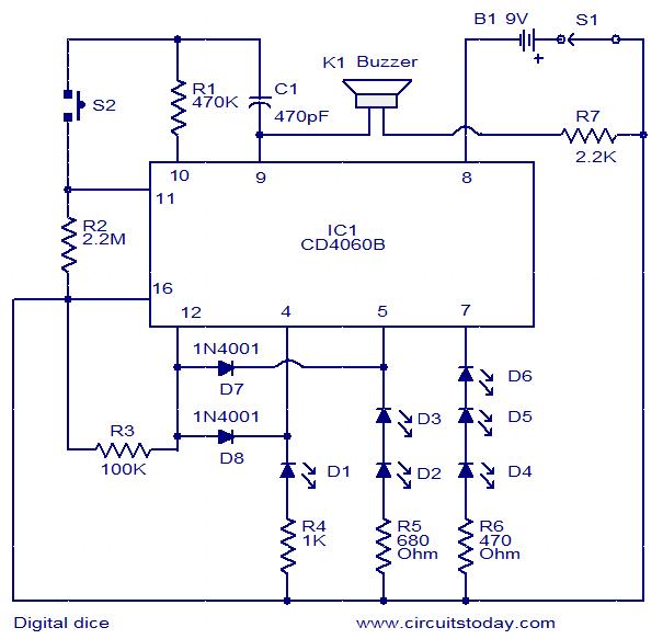
This is a simple and easy-to-construct digital dice circuit. The circuit is based on a single IC, CD4060B. The dice consists of six LEDs marked D1 to D6. The number of LEDs glowing indicates the numeral. The heart of...