
Tone encoder

The twin-T oscillator circuit is a well-known electronic configuration used for generating audio tones and frequencies. It typically consists of two resistors and two capacitors configured in a specific manner to create a notch filter that defines the frequency of oscillation. The output frequency is determined by the resistor and capacitor values, allowing for precise tuning of the desired tone.
In this circuit, the pushbuttons serve as momentary switches that activate the oscillator when pressed. Upon pressing a button, the circuit completes and the twin-T oscillator begins to produce a tone at the set frequency. Once the button is released, the circuit is interrupted, ceasing the tone generation. This functionality is ideal for applications such as sound effects in musical instruments or alert systems.
To implement this circuit, the resistors are typically connected in parallel with the capacitors, forming a feedback loop that sustains oscillation. The values of these components must be chosen carefully to achieve the desired frequency range. For example, using higher resistor values and lower capacitor values will result in higher frequencies, while lower resistor values and higher capacitor values will yield lower frequencies.
The output of the twin-T circuit can be connected to a speaker or an audio output device to produce audible tones. Additional components, such as amplifiers, may be incorporated to enhance the output signal for better sound quality. This circuit configuration allows for versatility in tone generation, making it suitable for various electronic projects and applications.A basic twin-T circuit uses resistors for accurately setting the frequency of the output tones, selected by pushbutton Momentary switches produce a tone only when the button is depressed.
Related Circuits
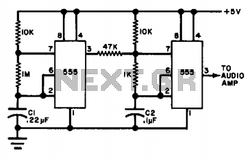
The circuit utilizes either two 555 timers or a single dual timer. Capacitor C1 regulates the speed of the warble effect, while capacitor C2 defines the pitch. The specified values are expected to generate a notably distinctive signal. The described...
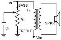
An audio tone control integrates both bass and treble controls within a single circuit. Such tone controls are typically found in lower-end audio equipment, as they conserve front panel space and require only one control knob instead of two...
This circuit generates a double tone police sound and a single tone old ambulance sound. It is typically installed in battery-powered cars and motorcycles. The circuit utilizes a sound generator IC, such as the 555 timer or a dedicated sound...
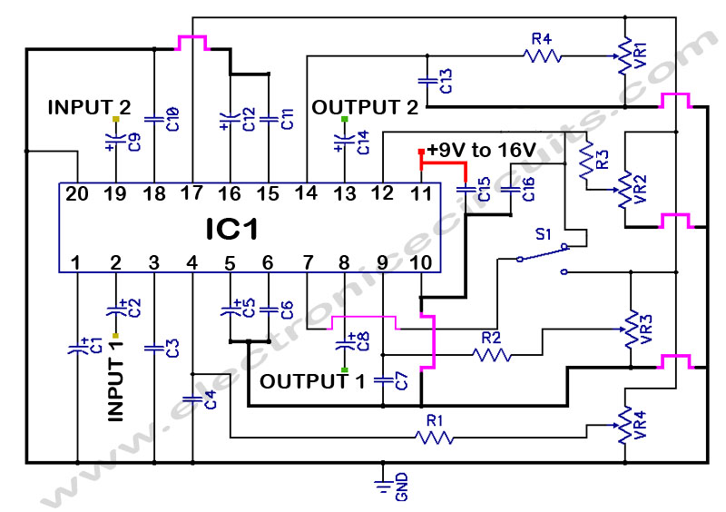
LM1036 Stereo Tone (Bass, Treble, Volume, Loudness, Balance) Controller Circuit. The LM1036 is a DC controlled tone (bass/treble), volume, and loudness controller designed for audio applications. The LM1036 circuit serves as an integrated solution for controlling various aspects of audio...
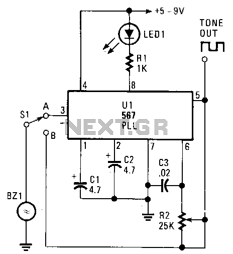
The transducer circuit can function as either a tone encoder or decoder by adjusting the position of switch Sl. The operating frequency of this dual-purpose circuit is set by capacitors C3 and resistor R2. Capacitors C1 and C2 are...
A tone control circuit is an electronic circuit designed to manipulate the tone of an audio signal. The tone of an audio signal is analogous to color in light. The tone control circuit typically consists of various components such as...