
Touch Sensitive On/Off Circuit 555 Timer

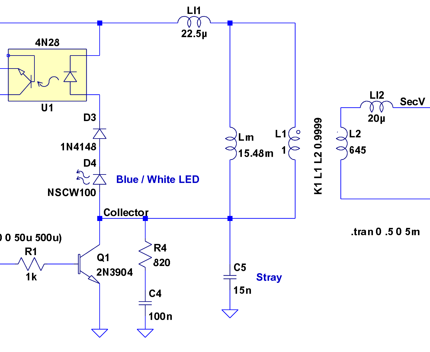
The circuit diagram serves as a crucial reference for accurately assembling electronic components in a project. It illustrates the arrangement and interconnections of various elements such as resistors, capacitors, diodes, and integrated circuits. Each component is typically represented by standardized symbols, allowing for easy identification.
In this case, the schematic includes detailed annotations indicating the values of components, such as resistance in ohms or capacitance in farads, along with the power supply specifications. The layout may also highlight the paths for current flow, ensuring that the user can trace the circuit effectively.
When following the tutorial video, it is imperative to cross-reference the diagram at each step of the assembly process. This practice minimizes the risk of errors, such as incorrect connections or component placements, which could lead to malfunction or damage to the circuit.
Additionally, attention should be given to the orientation of polarized components, such as electrolytic capacitors and diodes, as incorrect placements can result in circuit failure. Proper grounding techniques should also be observed, ensuring that all grounds are connected to a common point to avoid noise and interference.
In summary, utilizing the circuit diagram and schematic as a guide while assembling the project is essential for achieving a functional and reliable electronic circuit.Make sure to double-check your connections using the circuit diagram and schematic below. You can use this while you follow along in the tutorial vide.. 🔗 External reference
Related Circuits

A complementary voltage switching Class D amplifier circuit is presented. Transistors VT1 and VT2 are 3DA12 types, while another transistor, VT3, is of the 3DK41C type. The collector is connected to a constant DC voltage of 12V. The input...

The SLB0586A integrated circuit from Siemens can be utilized to construct a straightforward touch light dimmer circuit, enabling the user to modify the intensity of a lamp. This circuit also incorporates a TIC206D component. The SLB0586A is a specialized touch-sensitive...

The circuit consists of two light-emitting diodes (D1 and D2) whose operation is controlled by the ambient temperature. A temperature sensor, the LM35, generates an output of 10 mV for each degree of temperature increase. A reference potentiometer, R2,...
The yellow wires on the far right serve as temporary power connections, allowing battery power to enter through the contact studs located in the large holes that press against the radio's battery terminals. The cable in the lower right...
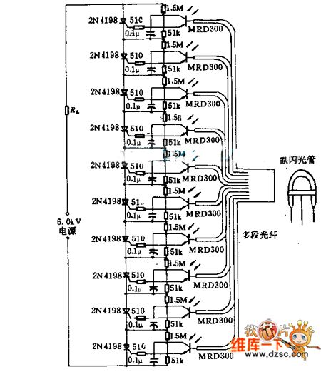
Light emitted by a Xenon flash tube is transmitted to the phototransistor MRD300 through an optical fiber. The sensitive current is amplified to trigger a series of thyristors simultaneously. Consequently, a high voltage of 6000V is applied to loader...

A tremolo circuit is a type of sound effect commonly utilized in guitar effect pedals. This effect is achieved by modulating the amplitude of an audio signal. The shape of the modulating signal can vary and may include square...