
Light emitting diode circuit of the temperature control

The circuit operates as a temperature-based LED indicator system, leveraging the characteristics of the LM35 temperature sensor and the CA3130 operational amplifier. The LM35 outputs a voltage proportional to the temperature, allowing for precise temperature monitoring. The choice of a reference voltage of 0.8 V is critical, as it establishes the threshold temperature at which the circuit will activate. When the LM35 output reaches this reference, the operational amplifier switches its output high, indicating that the temperature has exceeded the set point.
Transistors Q1 and Q2 are configured in a manner that ensures only one LED is illuminated at a time, providing a clear visual indication of temperature status. The circuit's design allows for easy adjustment of the trip point using the potentiometer R2, enabling flexibility in temperature settings based on specific requirements. The use of a stable power supply, provided by IC1, ensures reliable operation of the entire circuit, while the assembly precautions emphasize the importance of proper circuit construction and component placement to avoid malfunctions.
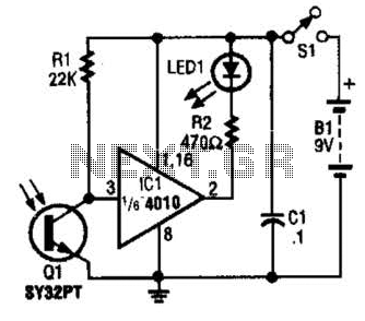
Overall, this circuit is suitable for applications where visual temperature monitoring is necessary, such as in temperature-sensitive environments or for educational purposes in demonstrating temperature sensing and control principles.Explanation The circuit is nothing more than two light emitting diodes (D1 and D2), its position is controlled by the temperature of the surrounding environment. Here the tempe rature sensor known as the IC LM35. LM35 increase the output of 10mV per degree of temperature rise. You can use the desired reference potentiometer R2 to the output voltage of the LM35 given the non-inverting input is connected to the same operational amplifier inverting input of the operational amplifier CA3130.The. If the reference voltage is 0.8V, then the non-inverting input terminal (LM35 output) voltage becomes 0.8V, when the temperature is 80 degrees Celsius.
Then the output of IC3 to positive saturation. This makes the transistors Q1 and D1 LED lights glow. Since the basis of the second quarter, Q1 is connected to the collector of the second quarter will close LED D2 remains closed. When the temperature is below 80 degrees Celsius reverse happens.IC1, produce a stable 5V DC working available9V DC supply voltage.
If you already have a 5V DC power supply, then you can use it directly. Schematic Precautions The circuit board assembly in Verona. IC3 holder must be installed. You can adjust the settings POTR2 temperature trip point. Type no Q1 and Q2 is critical. Any common NPN transistors will do it.
Related Circuits

An automatic light control circuit is designed to illuminate a lamp when it is dark and to turn off the light at daybreak. The circuit, as shown in Figure 2-86, employs bidirectional thyristor tubes and features a straightforward design....

The sound produced imitates the rise and fall of an American police siren. When first switched on, the 10 µF capacitor is discharged, and both transistors are off. When the push button switch is pressed, the 10 µF capacitor...
The loop can be any type of hookup wire, with a maximum resistance of about 90K. Using very thin wire (40AWG, for example) will create a highly sensitive trip wire, but will reduce the distance it can be strung...
This project page has evolved into a design discussion. Constructive suggestions and collaboration are still welcome. Please refer to the comments section. The project focuses on the development of an electronic circuit design, which has transitioned from a simple project...

This section is designed to amplify the signal until it reaches the required level. The IF amplifier is equipped with an Automatic Gain Controller (AGC) that regulates the amplification to ensure a constant amplitude output for the video. The...
The IR Tester circuit indicates whether the button pressed on a remote control is functioning. Q1 is a phototransistor that is activated by infrared (IR) energy. The IR Tester circuit operates by detecting infrared signals emitted by remote control devices...