
Touch Switch Circuit

The circuit described operates as a touch-sensitive switch using a combination of operational amplifiers and a triac-based lamp driver. The primary component, U1, is responsible for detecting the touch input and controlling the output states. When the touch-on contacts are bridged, a low signal at pin 6 of U1 indicates activation. This results in a high output at pin 4, which splits into two distinct paths.
The first path involves the output being applied to pin 2 of U1. This action leads to a low output at pin 3, which is then fed back to pin 5 of U1, ensuring that the operational amplifier latches in a high output state. This feedback mechanism is crucial for maintaining the output state even after the initial touch is removed.
The second path utilizes the output from U1 to drive transistor Q1. When Q1 is activated, it energizes U2's internal LED. The illumination of the LED triggers U2's light-sensitive triac-driver, which is designed to control larger loads. This triac driver feeds gate current to TR1, which is a triac responsible for switching on the connected lamp (L1).
The circuit's operation can be toggled off by bridging the off contact, which causes the output from U1 to switch states. The output at pin 3 goes high, resulting in a low output at pin 4, effectively turning off the lamp. This design allows for both touch activation and deactivation of the lamp, providing a user-friendly interface for controlling lighting based on touch input. The use of operational amplifiers, transistors, and a triac driver exemplifies a robust approach to creating a touch-sensitive control system for lighting applications. When the touch-on contacts are bridged, pin 6 of Ul-b goes low, which forces its output (the set output) at pin 4 to go high. That high divides along two paths; in one path, the output is applied to pin 2 of Ul-a, which causes its output at pin 3 to go low.
That low is, in turn, applied to pin 5 of Ul-b, which latches the gate in a high output state. In the other path, the output of Ul-b is used to drive Ql. When Ql turns on, U2`s internal LED lights, which turns on its internal, light-sensitive, triac-driver (diac) output element. The triac driver feeds gate current to TR1, causing it to turn on, and light the lamp (11). When the off contact is bridged, IJl-a`s output switches and latches high, causing Ul-b`s output to go low, turning off the lamp.
Related Circuits

This alarm system utilizes a loud police siren to deter potential intruders. Activated by a single clap, the circuit triggers the alarm for three minutes, which is adequate to alert nearby residents. The design incorporates a sensitive clap switch...

This tracking transmitter consists of four distinct subassemblies: a free-running multivibrator, a transmit switch, an audio-tone generator, and an FM transmitter. The multivibrator, which produces a pulse width with a pulse separation of 1500 ms, is built around Q1...
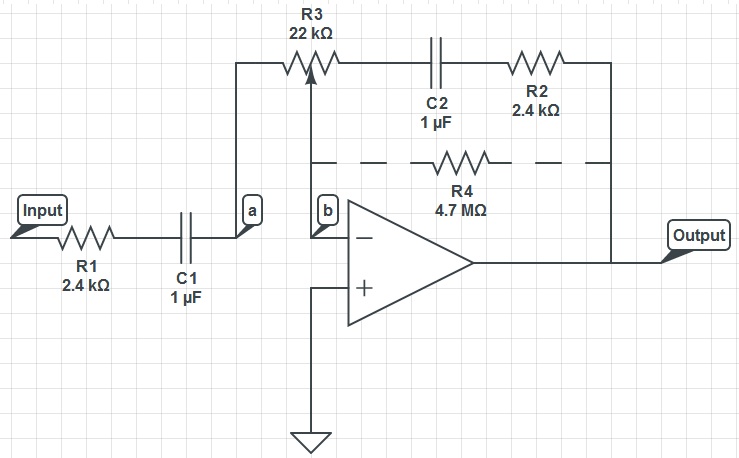
This circuit can function as a treble control circuit, with high-frequency gain occurring when resistor R3 is set to a value that makes points a and b equal (denoted as k=0). Conversely, high-frequency attenuation occurs when R3 is set...
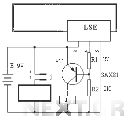
The circuit operation principle of the device illustrated in Figure 13 is as follows: When the barbed wire (Fe) remains intact, the output pin (O) of the LSE is at a high state. Consequently, the transistor (VT) remains off,...

This is a simple hobby circuit for a remote-controlled toy car. The primary component utilized is the IR sensor circuit, which includes a TSOP IR receiver. This receiver allows the user to start and stop the DC motor of...
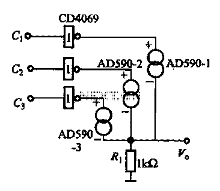
The AD590 is illustrated in a basic application circuit. As the AD590 provides a current output, a series resistance is used to convert this output current into a voltage. In the circuit, RP serves as the output voltage (vo)...