
Touch Switch Using Cd4066B Circuit

The described circuit employs a touch-sensitive switch SI that triggers a relay or electronic switch mechanism. Upon activation of SI, the resistor R4 is subjected to a high voltage, which indicates that a sufficient current is flowing through R4. This increase in voltage at the control input enables the latching mechanism to engage, maintaining the switch in an 'on' state even after the initial touch is released.
The inclusion of switch S2 serves as a reset or deactivation feature. When S2 is activated, it pulls the voltage at R4 low, effectively reducing the control voltage to a level where the latching mechanism is disengaged. This action breaks the circuit, returning the switch to its 'off' state.
The circuit's design is beneficial for applications requiring a momentary activation with a persistent output, such as in lighting control systems or automated devices. The use of resistors in conjunction with switches allows for simple yet effective control logic, ensuring that user interaction is intuitive and responsive. Proper selection of resistor values and switch types is critical to achieve the desired sensitivity and operational reliability in the circuit. When touch switch SI is activated, R4 is driven high, and the control voltage goes high, which latches the switch. When S2 is activated, R4 goes low and the control voltage goes low, which deactivates the switch.
Related Circuits
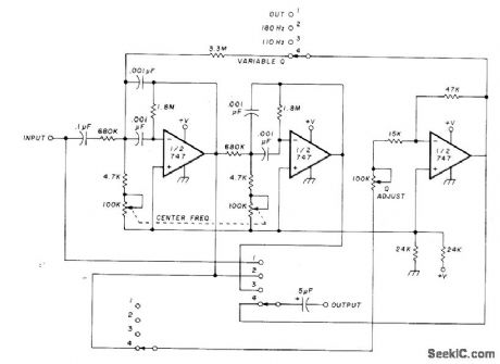
The circuit utilizing Optical Electronics 9803 operational amplifiers separates an audio frequency (AF) input signal into two outputs. The low-pass output allows frequencies from DC up to 10 Hz, while the high-pass output encompasses frequency content above 10 Hz,...

This design outlines a high impedance DC voltmeter circuit utilizing the uA741 integrated circuit (IC). The uA741 is configured as a non-inverting DC amplifier. The circuit incorporates negative feedback through a DC meter that requires 1 mA for full-scale...

This is a simple VE7GC Popcorn RF preamplifier designed by Dick Pattinson. The circuit features a single tuned circuit at the input stage, allowing direct connection to a mixer or product detector in a straightforward receiver project. Adjustable RF...
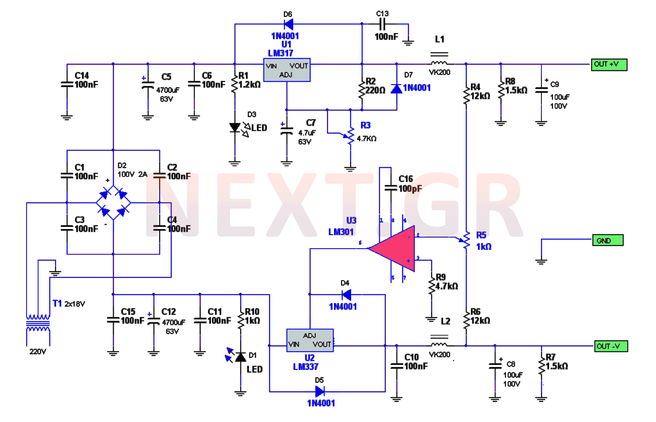
The power supply circuitry includes a 220/2 * 18V / 3.5A transformer, a rectifier, a smoothing filter, a power amplifier (LM301), and two regulators (LM317 and LM337). The voltage from the transformer is rectified by a bridge rectifier. Capacitors...
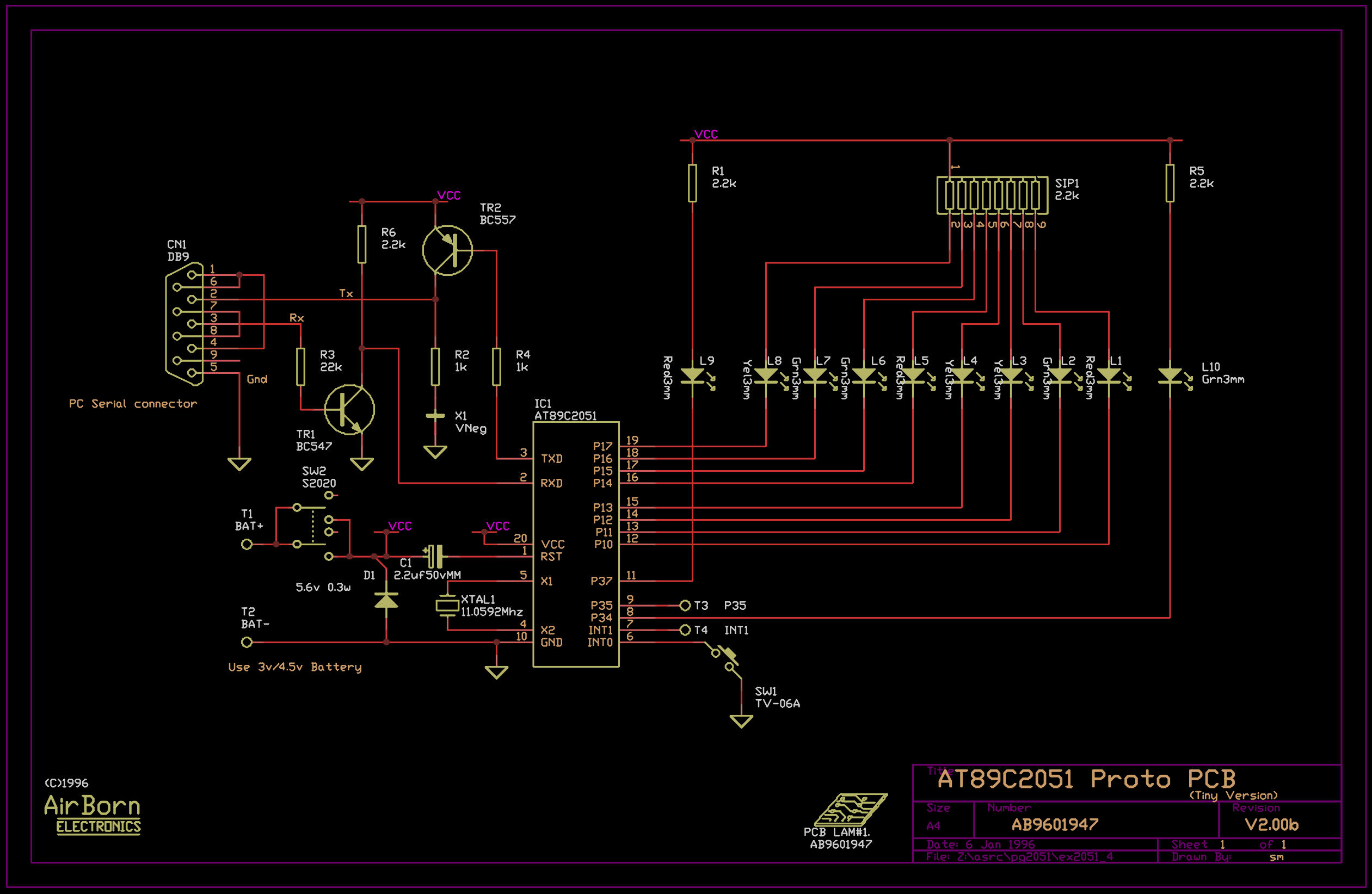
The example program included with the PG2051 evaluation kit is a basic serial to parallel converter written in 8051 assembler. This is probably a good example of the uses to which an AT89C2051 can be put - it would...
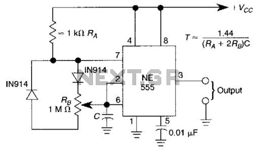
A 1.2-kHz oscillator utilizing a potentiometer and steering diodes allows for a duty cycle adjustment ranging from 1% to 99%. The frequency can be altered by varying the capacitor CI. It is important to note that the diodes may...