
High Impedance DC Voltmeter Circuit Using Op Amp

The high impedance DC voltmeter circuit is designed for accurate voltage measurements across a wide range of input voltages while minimizing loading effects on the circuit under test. The uA741 op-amp is selected for its favorable characteristics, including low input bias current and high input impedance, which is essential for high impedance applications. The non-inverting configuration allows for a straightforward voltage gain setup, where the gain can be adjusted by selecting appropriate values for resistors R1 and R2, thus enabling the user to switch between different voltage measurement ranges efficiently.
The feedback mechanism through R6 ensures that the meter's full-scale deflection occurs at a specific input voltage, enhancing the precision of the measurement. The specified 0.1 volts drop across R6 allows for a clear and consistent reference point for calibration. The inclusion of protective diodes (D1, D2, D3, and D4) is critical for enhancing the robustness of the circuit. These diodes prevent damage from overvoltage conditions, ensuring that both the IC and the measuring meter remain operational under adverse conditions.
The dual power supply configuration (+9V/-9V) is advantageous as it provides the necessary headroom for the op-amp to function effectively, allowing it to handle both positive and negative input voltages without distortion. This further ensures that the voltmeter can accurately measure AC signals when appropriately configured, making it versatile for various electronic testing applications. Overall, this high impedance DC voltmeter design is efficient, reliable, and suitable for laboratory and field use, capable of delivering precise voltage readings across a wide range of applications.This is a design for a high impedance DC voltmeter. This circuit is design with built by uA741 IC. This IC is a op-amp non-inverting DC amplifier. The IC have negative feedback that is through a DC meter requiring 1mA for full scale deflection. This is the figure of the circuit. The principle work of this circuit is since R6 is 100 Ohms, the meter will show full scale reading when the DC input voltage to pin3 is equal to the voltage drop across R6, viz 0. 1 volts. Choice of R1 and R2 for getting different voltage ranges are shown in the table. The diodes D1 and D2 protect the IC from accidental excessive input voltages and diodes D3 and D4 protect the meter from overloads.
The circuit can be powered from a +9V/-9V dual power supply. 🔗 External reference
Related Circuits
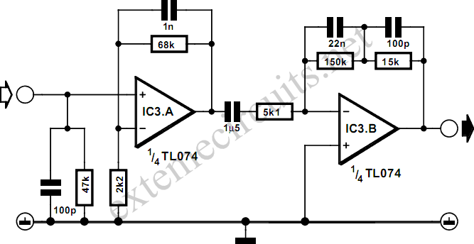
Modern sound systems often lack inputs for record players, leading to a rise in the popularity of separate MD preamplifiers. These devices are essential not only for vinyl enthusiasts but also for individuals looking to digitize their LP collections...
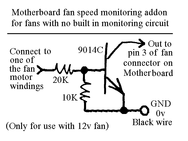
You will find this identical circuit inside most 3 wire computer fans with speed monitoring output to the motherboard. Peel off the sticker from the fan hub in order to access a motor winding pin for connecting up the...
This circuit utilizes the versatile MAX038 function generator. While some advanced features of this IC are disabled in this configuration, it can still generate sine, triangle, and square waves by adjusting the A0 and A1 pins (refer to the...
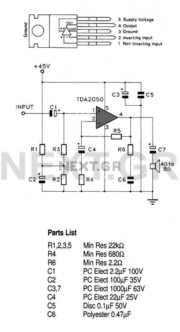
This circuit utilizes a high-quality audio amplifier integrated circuit (IC) housed in a 5-pin TO220 package, which eliminates the need for insulating washers between the metal tab and heatsink in single rail supply applications. The amplifier is capable of...
Crystal Y1 generates a fundamental frequency clock signal of 14.31818 MHz. U31 is a Dual Voltage Controlled Oscillator (VCO) that produces a 14.31818 MHz clock signal, referred to as the color clock, at pin 10. The output frequency can...
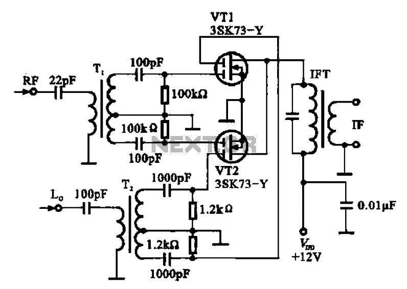
A balanced mixer circuit is illustrated using two dual-gate field effect transistors (FETs). The RF signal is coupled to the gates of these transistors through an input signal transformer (T1). Additionally, a local oscillation signal is introduced to the...