
Touch switching 12V Light

The described circuit employs two distinct configurations utilizing bipolar transistors and a power MOSFET to achieve touch-sensitive activation of a lamp. In the first configuration, three bipolar junction transistors (BJTs) are arranged in a cascading manner to amplify the small current generated by the human body's touch, which is typically in the microamp range. The touch contact is connected to the base of the first transistor, with the emitter connected to ground. The collector of the last transistor in the series can handle higher currents, allowing it to drive a load such as a lamp rated at 20 watts. The necessity of three transistors arises from the fact that each BJT has a limited current gain, usually below 200, thus multiple stages are required to achieve the necessary current amplification.
In the second configuration, a power MOSFET is utilized. The gate of the MOSFET is activated by a voltage of approximately 6 volts, which is achieved when the resistance across the touch contacts (around 2 Megohms) matches a fixed resistance connected between the gate and source. This configuration allows the MOSFET to remain in an off state until the touch contact is engaged, at which point the gate capacitance charges to the threshold voltage, turning the MOSFET on without drawing any current from the gate. This characteristic of the MOSFET is advantageous as it minimizes power loss during operation.
Both circuits are designed to be responsive to the relatively high skin resistance of 2 Megohms or less, ensuring functionality under typical conditions. For applications requiring higher current capabilities, the output load (a lamp in this case) can be substituted with a 12-volt relay, with a diode placed in parallel across the relay coil to protect against back EMF when the relay is deactivated. This design enhances the versatility and reliability of the circuit in various electronic applications.The circuit on the right uses three bipolar transistors to accomplish the same result with the touch contact referenced to the negative or ground end of the supply. Since the base of a bipolar transistor draws current and the current gain is usually less than 200, three transistors are needed to raise the microamp current level through the touch contacts to a couple amps needed by the light.
For additional current, the lamp could be replaced with a 12 volt relay and diode across the coil. The circuits below light a 20 watt lamp when the contacts are touched and the skin resistance is about 2 Megs or less. The circuit on the left uses a power MOSFET which turns on when the voltage between the source and gate is around 6 volts.
The gate of the MOSFET draws no current so the voltage on the gate will be half the supply voltage or 6 volts when the resistance across the touch contacts is equal to the fixed resistance (2 Megs) between the source and gate. 🔗 External reference
Related Circuits
This circuit effectively simulates various light sources such as a house fire, campfire, or welding light without the use of a microcontroller, although it requires a considerable number of components, including some uncommon ones. It is based on three...

This is the schematic of the conventional light dimmer. L1 and C2, C3 form the lichtnetontstoring. In this circuit meets almost every TRIAC as a TIC226D. For C1, C2 and C3 good capacitors (MKT example) with a minimum operating...
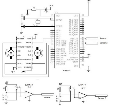
The electronic schematic of the Light Detector Robot can be divided into three main components: the sensor, the microcontroller, and the DC motor driver. The light sensor utilized in this design is a Light Dependent Resistor (LDR), which alters...
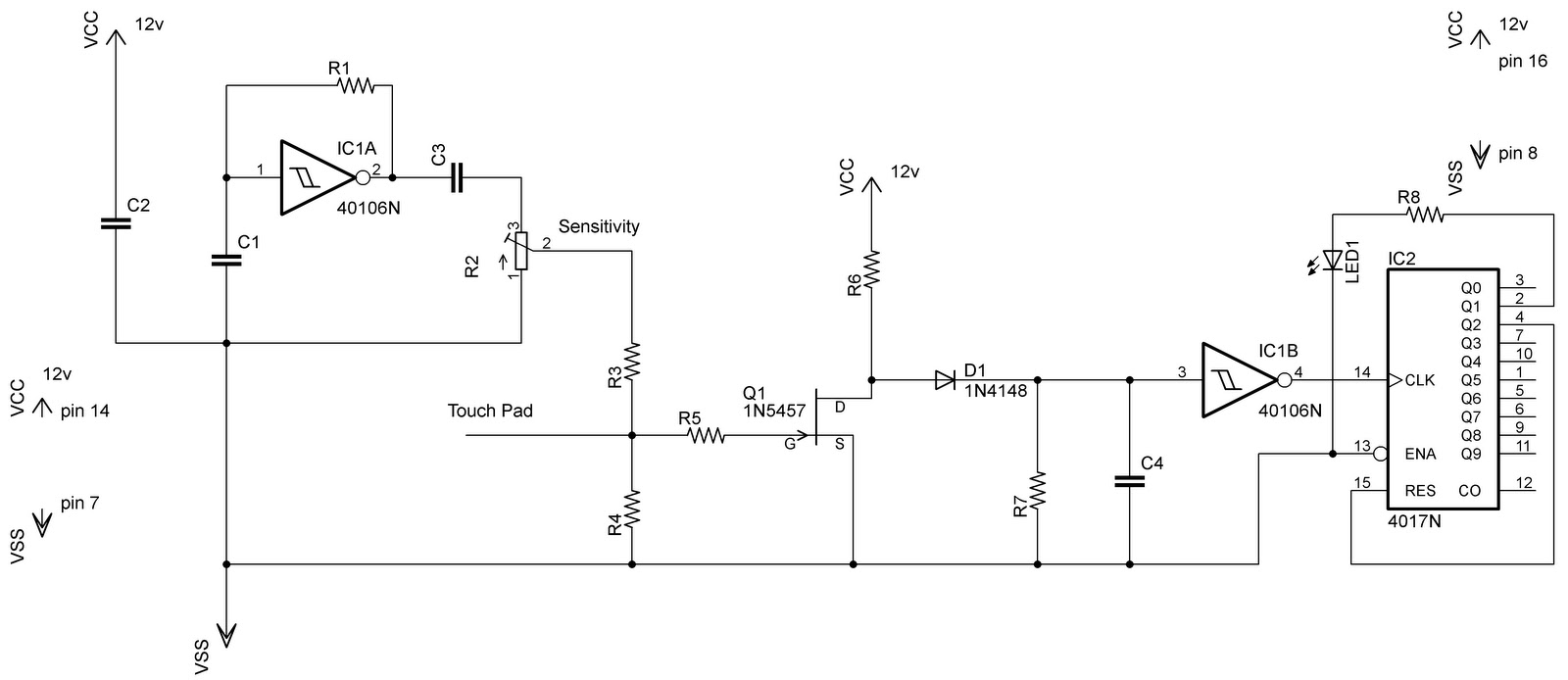
In the previous post regarding a capacitive touch switch, the output was activated only while the touch was maintained. This means that the circuit would drive the load only during the touch, and once the touch was removed, it...
This circuit provides a delayed visual indication when a door bell switch is pressed. In addition, a DPDT switch can be moved from within the house which will light a lamp in the door bell switch. The lamp can...

The Saver V5.0 operates a simple clock emulation program that controls a night light to turn on and off at preset times, specifically from 19:00 to 22:00 daily. This design is characterized by its low cost, easy installation, lack...